Download

1 / 84
850 likes | 1.22k Vues
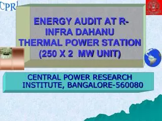
ENERGY AUDIT AT R-INFRA DAHANU THERMAL POWER STATION (250 X 2 MW UNIT). CENTRAL POWER RESEARCH INSTITUTE, BANGALORE-560080. DESIGN CAPACITY/ RATING OF DTPS. INSTALLED DURING BSES PERIOD 1995 TAKEN OVER BY R-INFRA IN 2003 NO MAJOR CHANGE IN HARDWARE SINCE

E N D
ENERGY AUDIT AT R-INFRA DAHANUTHERMAL POWER STATION (250 X 2 MW UNIT) CENTRAL POWER RESEARCH INSTITUTE, BANGALORE-560080
DESIGN CAPACITY/ RATING OF DTPS INSTALLED DURING BSES PERIOD 1995 TAKEN OVER BY R-INFRA IN 2003 NO MAJOR CHANGE IN HARDWARE SINCE IDENTICAL TO OVER 25 250 MW UNITS INSTALLED ALL OVER INDIA INCLUDING PARLI, PARAS & TATA TROMBAY. SAME DESIGN REPLICATED IN ALL UNITS PG TEST, INSTALLATION MANUALS, NAME PLATES, CAPACITY TESTS OF EQUIPMENT AND C & I INDICATE UNITS ARE OF 250 MW CAPACITY.
Rating Terminology • ‘Maximum Continuous Rating’ (MCR) of a generating unit means the normal rated full load MW output capacity of a Generating Unit which can be sustained on a continuous basis at specified conditions. Ref: [CENTRAL ELECTRICITY REGULATORY COMMISSION NOTIFICATION No. L/68(84)/2006-CERC New Delhi, the 14th March, 2006] Hence, 100 % MCR which refers to full load unit capacity is 100 % Unit MCR or 100 % UMCR.
Unit MCR (UMCR) refers to 100 % MCR of the unit. For the units under study UMCR is 250 MW. Boiler MCR (BMCR) refers to maximum rating of the boiler. The boiler rating corresponding to 100 % UMCR (i.e., 250 MW) is called as NCR (normal continuous rating). BMCR is higher than NCR by 8-10 % usually. Turbine MCR (TMCR) refers to rating of the turbine corresponding to 100 % UMCR (i.e., 250 MW). VWO condition refers to turbine rating under valve wide open conditions which is higher than the 100 % UMCR by 5 % usually.
Generator ratings are given by apparent power (MVA) [vector sum of active power + reactive power] at a given power factor and not by active power (MW) (power capable of doing work). This is because reactive power (power to overcome inductance or electrical inertia in the system) in the system also generates heat. • Generator transformers are rated by apparent power (MVA) and not by active power as reactive power (power to overcome inductance) also generates heat.
Overload capability of generating units: Each Generating Unit shall be capable of instantaneously increasing output by 5% when the frequency falls limited to 105% MCR. Ramping back to the previous MW level (in case the increased output level can not be sustained) shall not be faster than 1% per minute. Ref: [CEA Indian Electricity Grid Code, 2005]
All Generating Units, operating at or up to 100% of their Maximum Continuous Rating (MCR) shall normally be capable of (and shall not in any way be prevented from) instantaneously picking up five per cent (5%) extra load when frequency falls due to a system contingency. The generating units operating at above 100% of their MCR shall be capable of (and shall not be prevented from) going at least up to 105% of their MCR when frequency falls suddenly. After an increase in generation as above, a generating unit may ramp back to the original level at a rate of about one percent (1%) per minute, in case continued operation at the increased level is not sustainable. Ref: [CEA Indian Electricity Grid Code, 2005]
All machines are provided with peak plant load capabilities which are configured by the OEM (original equipment manufacturer) as continuous peak load (without impairing equipment life) and peak load for limited periods (with the effect of reducing the operating life of the equipment due to its effect on other quality parameters). When operating on continuous peak load duty OEM has ensured that all quality parameters are within safe limits and there is no acceleration of ageing/life reducing effect to the equipment for indefinite duration. Continuous peak plant load duty is denoted as follows: Boilers: BMCR rating Turbines: VWO rating Generators: MVA rating Generating transformers: MVA rating
Plant load (active power or MW) dependent and plant load independent parameters: In all coal fired thermal power plants the majority of the quality parameters like temperature, pressure (except for variable pressure operation), voltage, etc., are designed by the OEM to be nearly constant and first order load independent for the load range of 60 % UMCR through maximum load and changes are only second order. However, the quantity parameters like flow, current, etc. are directly proportional to active power (MW) or plant load or machine loading. As energy efficiency increases these quantities decrease in magnitude for a given output.
Hence, the plant load limiting parameters are primarily the quantity parameters like flow and current. As the energy efficiency of the equipment decreases these quantity parameters for a given output will increase thereby limiting their maximum values and posing a limitation on the maximum loadability of the unit. The other quality parameters like temperatures, pressures, voltages, etc., are designed to be load independent.
Peak parameters for limited periods are defined in terms of permissible peak loading of certain identified parameters such as currents, voltages, temperatures, pressures, flows, etc. and the time limits in seconds, minutes or hours in one excursion as well as total time in the lifetime of the equipment. Hence OEM has defined the parameters which constitute peak parameter loading along with the time for single excursion as well as the operating duration in the total lifetime of the machine. Continuous peak parameter loading is done purposefully for achieving the maximum performance or output from the machine whereas the limited period peak parameter loading occurs because of system operational transients or constraints or limitations or system mismatch. When parameters go out of operating range or out of control, then a transient results which amounts to limited period peak parameter loading.
TESTS ON UNITS • Maximum load- 268 MW • 100 % UMCR- 250 MW • F-GRADE LOAD- MAXIMUM LOAD REACHED WAS 240 MW
BOILERS NCR (normal continuous rating) refers to steaming requirements which correspond to 100 % UMCR (250 MW). Boiler MCR or BMCR refers to steaming requirements for valve wide open condition of the turbine + auxiliary steam + operating margin. This will normally be around 8-12 % higher than the 100 % UMCR capacity. Hence, boilers have operating margins of 8-12 % above the 100 % UMCR capacity (i.e., steam requirement at 250 MW).
BOILERS BMCRcapacity consists of: 102 % of steam flow at HP turbine throttle inlet under turbine valve wide open (VWO) condition, 7.18 kPa (69 mm Hg) condenser pressure 3% cycle make-up (to compensate for steam lost through the system) 20 t/h steam for meeting normal auxiliary steam requirements of the unit (steam which is used for non-motive purposes).
BOILERS In other words, the boiler maximum steaming rates (BMCR) are designed (continuous rating) at: 7.1 % additional steam flow over and above the 100 % NCR flow (2 % over 105 % for VWO condition of turbine =1.071) 3 % make up which amounts to =0.03. The boiler is also capable of supplying auxiliary steam (20 t/h) of 2.67 % of the NCR flow. If the auxiliary steam is drawn from another boiler or another source or is minimized by best practices this will provide an additional margin up to 2.67 %.
BOILERS Thus, most boilers have a margin of around 7 % with additional margin of around 3-4 % if DM water and auxiliary steam are prudently utilized and minimized with reference to the design value.
BOILERS Another important factor (besides high energy efficiency) which governs the capacity is the design coal GCV of the boiler and the operating GCV. The operating GCV must always be higher than the design GCV if the boiler is to be used effectively. If the operating GCV of the boiler is lower than the design GCV then the firing rate will have to be increased
Effect of GCV on loading rate or steaming rate of the boiler: Coal firing rate (t/h) = 317.38 – 0.0421[(GCV) (kcal/kg)] Effect of GCV on specific fuel consumption (SFC): SFC (kg/kWh) = 1.1869 – 0.00021[(GCV) (kcal/kg)] Effect of GCV on boiler efficiency: Boiler efficiency (%) = 84.046 +0.001[(GCV) (kcal/kg)] (valid up to 5000 kcal/kg) Effect of GCV on UHR: The UHR decreases with GCV and the sensitivity index is -0.0968 kcal/kWh per kcal/kg: UHR (kcal/kWh) = 2643.7-0.0968 [(GCV) (kcal/kg)] (valid up to 5000 kcal/kg)
Study of operational parameters The operational parameters of the boiler be classified into two types: Continuous normal and continuous overload parameters with no time restriction on them. Overload parameters with restriction on a single excursion as well as total time in the life of the unit. There are two types of parameters in a boiler: Quantity parameters (like flow, current, etc.) which are directly plant load dependent Quality parameters (like temperature, voltage, pressure, etc.) which are designed to be plant load independent for the load range 60 % UMCR through maximum load.
Study of operational parametersOn scrutiny of the data it is seen that the DTPS has not exceeded any parameter beyond the values set by the OEM and they have set alarms and trippings for parameters well within the limits set by OEM for asset management and asset preservation. It is ensured that restricted time overload parameters are never reached control action in the form of alarms and tripping is designed to be activated well before they are reached. All control loops are in action and continuous recording of all data is available including water chemistry data.
DTPS boilers are designed for BMCR of 805 t/h & design steam flow at 250 MW is 746 t/h. As per the study it is seen, DTPS has ensured that boilers are operated well within BMCR design limit. Steam flow from the boiler is being monitored on real time basis through DCS and the limit of < 775 t/h- priority 1 Alarms are configured in HMI Also daily/monthly/yearly basis deviation report is reviewed and all parameters are being recorded and ensured to be within limits. Better quality of coal (Blend Indian washed coal with imported coal) which is higher than the design GCV by 600-800 kcal/kg also contributes in maintaining high steaming rate of the boiler besides the high boiler efficiency. In conclusion, it can be said that the DTPS has been able to maintain steaming rates below the BMCR levels prescribed by OEM while simultaneously not overloading any parameter beyond OEM limits through: High boiler efficiency (85.35 %) High GCV of coal (600-800 kcal/kg above the design value) Minimizing auxiliary steam requirements
TURBINES The terminology to designate capacity of turbines is as follows: TMCR refers to steam demand for 100 % UMCR VWO (valve wide open) condition of the turbine refers to steam demand when the turbine valves are fully opened. These are normally 5 % over and above the 100 % UMCR capacity. Hence turbines have operating margins of 5 % above the 100 % UMCR capacity. The turbines are sized such that they shall be capable of operating continuously with valves wide open (VWO) at rated main steam and reheat steam parameters. The total steam flow to turbine is the steam flow at HP turbine stop valve inlet plus external steam supplied to the turbine cycle such as gland steam, stack steam, etc.
TURBINES However, it is common experience that most Siemens turbines have continuous overload margins up to 8 %, that is, 210 MW operate at up to 227 MW. Siemens turbines normally have a built in margin of 15 % in torque. It has been clarified from turbine specialists that turbines have margins up to 15 % in power output without any harmful effect provided efficiency and steam cleanliness is maintained. Since turbines are constant speed machines with load directly proportional to the transmitted torque, the heat generation in the journal bearings is second order dependent on load while the heat generation in thrust bearings is directly proportional to load. If the turbine efficiency is maintained very near the design value, then the heat generation in the thrust bearings can be kept well within OEM limits even with high load ability.
TURBINES Apart from maintaining the load ability of turbines, DTPS has made provisions to supply the required steam through: minimized auxiliary steam flow (by cutting down on tracing steam for HFO and introducing zero steam leak policy) minimized DM water consumption (by cutting down steam lost to the atmosphere) minimized auxiliary steam consumption in the turbine itself (for gland sealing steam, stack steam and vent steam) to ensure that most steam goes into the turbine and turbine load ability further improves. DTPS has ensured turbine load ability of more than 100% TMCR by some additional measures such as the following: Good condenser vacuum due to open cycle operation of condenser cooling & by use of sea water for condenser cooling. Rated parameters of equipments are never violated & regular monitoring of same through deviation report thereby preventing parameter excursions and loss of value of the asset. Maintaining very good quality of process chemistry parameters of steam and water Program of routine, preventive, predictive maintenance and planned AOH. Continuous monitoring of process cycle efficiency on line & off line. Simulator training for operators using the customized 250 MW simulator.
TURBINES In conclusion it can be said that the DTPS has be able to maintain good load ability on the machine within the OEM margins and without exceeding any OEM parameter limits by: Maintaining high turbine efficiency (turbine heat rate deviates from design by only 4.4 kcal/kWh) Strictly maintaining water quality parameters as per OEM guidelines Minimizing auxiliary stack, vent and gland sealing steam requirements in the turbine.
TURBINES All turbine related flow, pressure (except for variable pressure operation), temperature, vibration and position parameters are archived for past two years in EXCEL files. In additional the water chemistry parameters such as electrical conductivity, pH, silica and chlorides have been archived for the last 2 years on daily average as well as hourly basis for 2009 and 2010. Figures 77-91 give the turbine steam, oil and metal parameters including mechanical parameters such as vibration, axial shift, etc., over the past one year on a daily average basis for Unit 1. Similar data is also studied for Unit 2. The hourly average is also archived and studied for both Units 1 & 2 for 2 years (2009 & 2010). On scrutiny of the data it is seen that the DTPS has not exceeded any parameter beyond the values set by the OEM and they have set alarms and trippings for parameters well within the limits set by OEM for asset management and asset preservation. Restricted time overload parameters are never reached to preserve the value of the asset. Very good water chemistry parameters are being maintained. The parameters which have most critical effect on the life of the turbine are: Main steam and reheat temperature Main steam pressure
The schedule of tolerances in the generator must be as per IS 4722: 2001 and the operating specifications including combinations of parameters at any given output must be according to IS 5422: 1996 (reconfirmed 2002).
GENERATORS In conclusion it can be said that the operation of the generator at a load of 268.7 MW (108 % of the UMCR) without exceeding the OEM margin and without exceeding any parameter from OEM limits is possible because of: Power factor improvement from 0.85 to 0.99. High generator efficiency (as good as design efficiency) thereby reducing the current and heat generation.
GENERATOR TRANSFORMERS Generator transformer are rated by apparent power (MVA) and not by real power (MW). Generator transformers are normally rated at 7.1-10 % higher than the generator 100 % MCR MVA rating at the designed power factor. Generator transformers are designed for continuous operation at any tap at rated 315 MVA with voltage variation of ±10 % of rated tap voltage; and capable of delivering rated current at a voltage equal to 105 % of rated voltage without exceeding specified temperature rise giving a continuous overload capacity of 5 %.
If the power factor is improved from 0.85 to near 1.0 then a 15 % margins will be available to the station in the form of active power (MW) capacity. Thus, generator transformers have a margin of around 7-10 % with an additional margin if the power factor is increased from 0.85 to 0.99 as the capacity is controlled by the MVA rating and not the MW rating.
Thus the generator transformers have a margin of 7 % over the generator apparent power.
The generator transformer rating is 315 MVA. During the performance test the maximum load on generator was computed as 251.6 MVA (load factor: 79.87 %). The computed current was 667 A and is lower than the design value of 773.9 A. The GT winding temperature was in the range of 64 – 71 oC at power output of 265.5 MW during Test 1 and was lower than the design value of 55 oC above ambient temp. (during test ambient temp. was 31.25 oC). Similarly the GT oil temperature was in the range of 43 – 48 oC at power output of 265.5 MW during Test 1 and was lower than the design value of 50 oC above ambient temp. (during test ambient temp. was 31.25 oC).
LIFE LIMITING FACTORS The power plant assets (boiler, turbine, generators, major auxiliaries, etc.) are designed for an operational life of 3,00,000 (3 lakh) operating hours or around 35 years of service under normal operating regime. If the operating regime is deviated, the acceleration of ageing takes place and the operational life gets reduced. In other words, the equipments get due for replacements much sooner than expectations.