ECG Basics Module 1
ECG Basics Module 1. Dr. Jeffrey Elliot Field, HBSc. DDS, Fellow, American Dental Society of Anesthesia Diploma, the National Dental Board of Anesthesia. 1. 11/13/2014. Introduction to Module 1. 2. 11/13/2014. Objectives. 3. 1) To learn how to properly set up your ECG leads.

ECG Basics Module 1
E N D
Presentation Transcript
ECG Basics Module 1 Dr. Jeffrey Elliot Field, HBSc. DDS, Fellow, American Dental Society of Anesthesia Diploma, the National Dental Board of Anesthesia. • 1 11/13/2014
Introduction to Module 1 • 2 11/13/2014
Objectives • 3 1) To learn how to properly set up your ECG leads. 2)To Learn What a lead is. 3)To learn the anatomy of a normal ECG. 4) To define Normal Sinus Rhythm. 5) To quantify the various components of a normal ECG 11/13/2014
EQUIPMENT • 4 The “Three Lead” ECG utilized in most offices for dental procedures. However more and more practioners are using 5 lead ECG’s. 11/13/2014
What IS A LEAD ? The term lead refers to the placement of electrodes in relationship to the heart. By looking at the electrical potential differences from different placements of positive and negative leads/electrodes one can get a view of the electrical activity of different areas of the heart.
So think of lead one, lead two, lead three etc. simply as different views of the heart. • By knowing which area of the heart you are looking at you can more easily pinpoint the areas where arrhythmias originate
7 The five lead ECG is becoming a standard feature on all new monitors. The 7 leads you can monitor are: I II III AVR AVL AVF and one precordial lead (usually)V5 This allows more precise diagnosis of cardiac events 11/13/2014
Augmented Voltage Leads: aVR, aVL aVF; unipolar ; form a set of axes 60° apart but are rotated 30° from the axes of the standard limb leads.
Chest Leads: Vl, V2, V3, V4, V5, V6, explore the electrical activity of the heart in the horizontal plane; i.e., as if looking down on a cross section of the body at the level of the heart.
This is a 12 lead ECG or simply 12 different views of the heart.
Lead Placement for a 3 Lead ECG • 14 • Remember the pneumonic WHITE RIGHT RED RIBS BLACK LEFTOVER 11/13/2014
Lead Placement for Five Lead • 16 • WHITE RIGHT,RED RIBS,BLACK LEFTOVER, PLUS GREEN RIGHT RIBAND BROWN MID CHEST 11/13/2014
The Lead you are looking at depends on the charge of the leads in relationship to their position in the triangle. The following picture shows how the ECG machine changes the charges to show different leads. But the physical position of the white red and black leads does not change.
G G G Note the ground lead is in the 3rd position of the triangle ( G) • 19 11/13/2014
In Emergency • Patients can be monitored with only 2 Leads attached. • These is done either with the Defibrillator Paddles or with Defibrillator Patches
Note the placement in each case is upper right and lower left chest which will sandwich the heart in between the electrodes. Which coincidentally is one of the correct placements for defibrillation and will also work for external pacing .
Remember all that an ECG is looking at is the electrical activity and electical activity is not always associated with contraction. ( SEE EMD/PEA LATER). So never forget to check a manual pulse in an emergency.
The depolarization wave produces a wave of atrial contraction, which is called the P wave
The ventricular depolarization is represented by an abrupt waveform called QRS wave • Ventricular repolarization is represented by the T wave
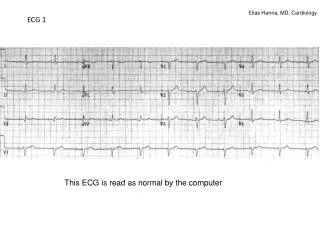
Normal Sinus Rhythm(Definition) -P-waves are regular and upright -Each P-wave is followed by a QRS Complex -QRS complex are regular at a rate of 60-100 beats per minute -T-waves are upright and follow the QRS complexes
Pacemaker Cells and Sites • Each area in the conduction system has its own inherent rate of firing in descending order from the SA Node. • If the area above a site fails to send an impulse ( or that impulse is blocked) the next pacemaker site will take over. • Therefore by knowing the rates of each site you can get another clue as to the area of damage
THERE ARE 5 COMPONENTS TO A RYTHYM STRIP P Q R S T
P WAVE The P wave represents atrial depolarization
Q WAVE • Q wave is the first negative deflection prior to any R wave • This wave represents depolarization of the intraventricular septum
R WAVE • R wave is the first positive deflection • This represents depolarization of the bulk of the ventricular muscle.
S WAVE • S wave is the negative deflection following and R wave • It represents the late depolarization of the last bit of ventricular muscle.
T wave • 35 T wave represents ventricular repolarization. The ventricle prepares to fire again Normally upright in leads I, II, and V3-V6 Variable in the other leads III, AVL, AVF, and V1-V2 11/13/2014
Anatomy of an ECG (Normal Cardiac Timing/Intervals) • There are 6 intervals /timings during the cardiac cycle. All are important except for the T-wave interval which is usually not measured. • -P wave ( 0.1 seconds) • -PR interval ( 0.12-0.2 seconds) • -Q wave ( 1 small box deep {0.04 sec} or less than 25% of the R-wave) • -QRS interval ( 0.10 second) • QT interval (0.425 seconds) • -T wave ( not usually measured)
Time Sequences on ECG Strips • The strip is read from left to right in seconds and up and down on millivolts.
P Wave Size and Morphology • Normal duration is less than 0.11 seconds wide( or 3 small boxes) and less than 2.5 mv high or less than 2.5 boxes high. • The P-wave should be upright in leads II, III, and AVF • Over 0.12 suggests an intra-atrial conduction defect • The normal p-wave morphology looks like this.
Q wave • 44 • The Q-wave is the first negative deflection after the p-wave • It should not exceed 0.03-0.04 millivolts in length or 1 small box. • Pathological Q waves are defined as those that are 25% or more of the height of the R wave and/or greater than 0.04 seconds in height. 11/13/2014
T WAVE • Not usually measured but its morphology is looked at in evaluating potassium levels in patients-see a later module.
PR INTERVAL • Normal duration is 0.12-0.20 seconds or 4-5 small boxes • This interval is measured from the beginning of the p-wave to the beginiing of the Q-wave • This interval is used to diagnose heart blocks and accessory pathways
QRS INTERVAL • Normal is 0.10 or less than 3 small boxes. • Wide QRS complexes are indicative of a blockage at or above the AV node.
QT Interval • 49 Normal is below 0.425 seconds or around 10 small boxes. If abnormally prolonged or shortened, there is a risk of developing Ventricular Arrhythmias. 11/13/2014