Download

1 / 7
90 likes | 348 Vues
Airplane landing gear. By: Cole Stamper. Input. Steal Shaft Lathe Drill Air Compressor Sanders Digital micrometer. Water based coolant Cadmium Oven Liquid Nitrogen Workers Electric power. Process. Step 1: Place Steal rod in lathe

E N D
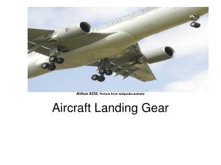
Airplane landing gear By: Cole Stamper
Input • Steal Shaft • Lathe • Drill • Air Compressor • Sanders • Digital micrometer • Water based coolant • Cadmium • Oven • Liquid Nitrogen • Workers • Electric power
Process • Step 1: Place Steal rod in lathe • Step 2: Use the Digital Lathe to machine the outside surface of the landing gear. • Step 3: Coolant is used to stop the parts from warping. • Step 4: Use drill head to hollow out the shaft to make room for the cylinder. • Step 5: Drill out a space for an attachment hole for a brace on its side.
Process • Step 6: Parts are cleaned out with a stream of compressed air. • Step 7: Now that the shaft is machined The part are sanded and polished to reduce friction on the parts. • Step 8: All parts are measured to ensure they meet regulations. • Step 9: All parts are immersed in cadmium and cerotic acid to reduce corrosion. • Step 10: Parts are placed in oven at 190 degrees for 24 hours then cooled to make it stronger.
Process • Step 10: Parts are placed in oven at 190 degrees for 24 hours then cooled to make it stronger. • Step 11:Leak proof joints and other components are inserted. • Step 12: shock absorbers are tested for leaks. • The final step: the parts are painted the reassembled.
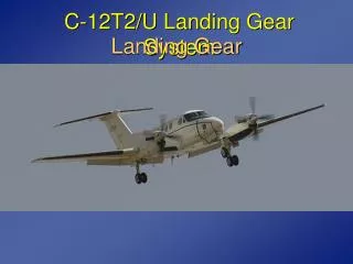
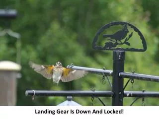
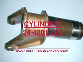
Output The final product looks like this.
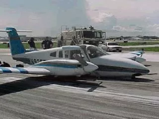
Feedback • The final product is tested and flaws would be reported to the company. • After flaws were recognized the design would change or the manufacturing process would be revised.