Global Positioning System (GPS)
Global Positioning System (GPS). GPS Satellite Constellation. 24 satellite constellation Semi-synchronous, circular orbits (~20,200 km/10,900 nautical miles altitude) Six orbital planes, inclined at 55 degrees, four vehicles per plane Repeating ground tracks (11 hours 58 minutes)

Global Positioning System (GPS)
E N D
Presentation Transcript
GPS Satellite Constellation • 24 satellite constellation • Semi-synchronous, circular orbits (~20,200 km/10,900 nautical miles altitude) • Six orbital planes, inclined at 55 degrees, four vehicles per plane • Repeating ground tracks (11 hours 58 minutes) • at least four satellites always in view • Cesium and/or rubidium clocks on board each operational satellite
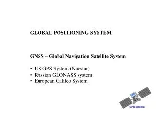
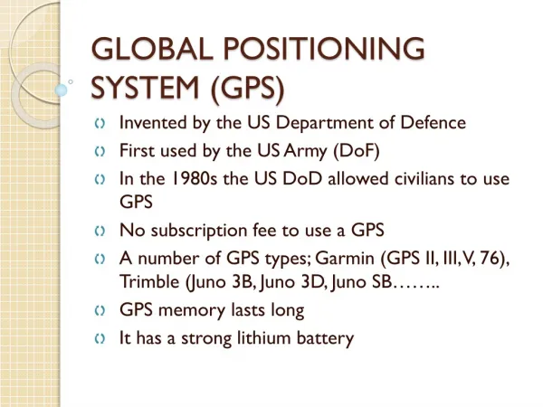
GPS History • Developed by the US Department of Defense • Early GPS program driver was Trident Missile Program (Submarine launched ICBM) • Precursors to GPS • Transit • Timation (first atomic frequency standards flown in space) • USAF 621B Program (PRN codes for ranging) • First prototype GPS satellite launched in 1978 • First Block II (Operational) GPS satellite launched 1989 • Full Operational Capability declared in 1994
Precise Timing is Fundamental to GPS • Assume the maximum acceptable error contribution from GPS satellite clocks is 1 meter • Light travels 3x10⁸ m/s, one-meter requirement equivalent to 3.3 ns ranging error • Clock error must be maintained below this level over 12 hour period (time between satellite uploads) • Requires a clock with < 1 part in 1013 stability, which can only be met by an atomic standard • Note: The frequency shift on the GPS satellite clock due to relativistic effects (special and general) is on the order of 4 to 5 parts in 1010
GPS Signal Structure • Two L-band carrier frequencies L1 = 1575.42 MHz L2 = 1227.60 MHz • Two PRN Codes • P(Y): Military Code • 267 day repeat interval • Encrypted – code sequence not published • Available on L1 and L2 • C/A: Coarse Acquisition (Civilian) Code • 1 millisecond repeat interval • Available to all users, but only on L1 • Code modulated with Navigation Message Data • Provides ephemeris data and clock corrections for the GPS satellites • Low data rate (50 bps)
Space Vehicles Block I Satellite – SVN 1 -12 1978-85 (none in service) Block 0 (NTS) Satellite Block IIR and IIR-M Satellites - SVN 41-62 1997-2005 (0 Cs and 3 Rb) Block II Satellite -SVN 13-21 1989-90 (2 Cs and 2 Rb) Block IIA Satellite - SVN 22-40 1990-1997 Block IIF and GPSIII Satellites SVN 63 - ?? 2005- ???? (3 Cs and 1 Rb)
Most GPSDOs receive the L1 carrier frequency at 1575.42 MHz The L1 carrier contains the C/A, or Coarse Acquisition Code 1 millisecond repeat interval 1023 bits Currently 29 satellites in orbit (all slots filled except PRNs 9, 12, and 32) 9 running off Cesium oscillators 20 running off Rubidium oscillators Block II/IIA Vehicles Block IIR Vehicles GPS Satellites
GPS Control Stations • Monitor Stations: Hawaii, Ascension Island, Diego Garcia, Kwajalein, and Colorado Springs • Monitor the GPS satellites for operational health • Track the GPS satellites for orbit determination • Upload navigation message data including satellite almanacs, ephemeris messages, and clock correction parameters
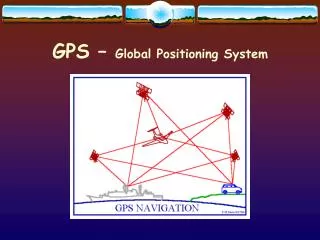
GPS Positioning • GPS-based positioning is fundamentally based on: • The precise measurement of time • The constancy of the speed of light • GPS-based positioning uses the concept of trilateration • GPS satellite positions are known • Receiver position is not • GPS-to-receiver range measurements are used to compute position
Positioning Example with 1 Transmitter Receiver(location unknown) Locus of points on which the receiver can be located Measured Range Transmitter(location known)
Positioning Example with 2 Transmitters True Receiver Location r1 r2 T1 T2 False Receiver Location
Positioning Example with 3 Transmitters True Receiver Location r3 T3 r1 T1 T2
GPS Positioning - II • The position solution involves solving for four unknowns: • Receiver position (x, y, z) • Receiver clock correction • Remember: Position accuracy of ~10 m implies knowledge of the receiver clock to within ~30 ns • Requires simultaneous measurements from four GPS satellites • The receiver makes a range measurement to the GPS satellite by measuring the signal propagation delay • The data message modulated on the GPS signals provides the precise location of the GPS satellite and corrections for the GPS satellite clock errors
Although the primary purpose of GPS is to serve as a positioning and radionavigation system, the entire system relies on precise timing. After the receiver position (x, y, z) is solved for, the solution is stored. Then, given the travel time of the signals (observed) and the exact time when the signal left the satellite (given), time from the atomic clocks (either cesium or rubidium) onboard the satellites can be transferred to the receiver clock. The basic measurement made by the GPS receiver reveals the difference between the satellite clock and the receiver clock. This measurement, when multiplied by the speed of light, produces not the true geometric range but rather the pseudorange, with deviations introduced by the lack of time synchronization between the satellite clock and the receiver clock, by delays introduced by the ionosphere and troposphere, and by multipath and receiver noise. The equation for the pseudorange observable is p = ρ + c × (dt − dT ) + dion + dtrop + rn where p is the pseudorange, c is the speed of light, ρ is the geometric range to the satellite, dt and dT are the time offsets of the satellite and receiver clocks with respect to GPS time, dion isthe delay through the ionosphere, dtrop is the delay through the troposphere, and rn represents the effects of receiver and antenna noise, including multipath. An estimate of dion is obtained from the GPS broadcast.
GPS Modulation • The carriers are pure sinusoids. Two binary codes are modulated onto them: the C/A (coarse/acquistion) code and the P (precise) code. • Binary biphase modulation (also known as binary phase shift keying [BPSK]) is the technique used to modulate the codes onto the carrier. There is a 180 degree carrier phase shift each time the code state changes. • The modulation requires a much wider frequency band than the minimum bandwidth required to transmit the information being sent. This is known as spread spectrum modulation. It allows lower power levels to be used.
Spread Spectrum Communication • “Spreads" the power spectrum of the transmitted data over a wide frequency band • Same principle is used for digital phones (voice is the data) • Each satellite is assigned unique Pseudo-Random Noise (PRN) Code • Allows Multiple Access – All GPS satellites transmit at the same frequency
Spread Spectrum Communication - II • The transmitted signal is the product of the navigation data, a spreading code, and the RF carrier (either L1 or L2) • In order to detect the GPS signal and recover the navigation data, the receiver must produce a replica of the PRN code to mix with the incoming signal (PRN codes must be known) • The measured phase offset between the incoming and replica PRN code is the GPS range measurement
1. “Random” Binary Data Message Spectrum 0 Hz frequency 2. Data*Spreading Code Spectrum Signal is “Spread” frequency 0 Hz Why the name “Spread Spectrum”? Data Rate Spreading Code Rate In our example, the data would be spread across 3 times the bandwidth of the data
Spectrum chart of GPS L1 Signal 1. Data Message Spectrum 0 Hz 50 Hz frequency 2. Data*Code Spectrum Signal is “Spread” frequency 0 Hz 1.023 MHz 3. Data*Code*Carrier Spectrum 1.023 MHz This is the transmitted signal 1.57542 GHz 0 Hz
GPS Time • Controlled by the United States Naval Observatory (USNO), but not exactly the same thing as UTC(USNO). • GPS time differs from UTC by the number of leap seconds that have occurred since the origination of the GPS time scale (January 6, 1980); this value is equal to 13 s as of November 2005, it will become 14 s after the next leap second. The navigation message contains a leap second correction, however, and GPS receivers automatically correct the time-of-day solution. • It also differs from UTC(USNO) by a small number of nanoseconds that continuously changes. The current difference between the UTC(USNO) estimate and GPS time is also in the navigation message, and this correction is applied to the 1 pps signal. • After the leap second and UTC(USNO) corrections are applied, GPS time is usually within 30 nanoseconds of UTC, UTC(NIST), and UTC(USNO). This makes it the best estimate of UTC being broadcast anywhere, and it is available free of change to anyone, worldwide. • The frequency offset between the UTC(USNO) estimate and UTC(NIST) is very small, typically a few parts in 1015 or less when measured over a one month interval.
Factors limiting uncertainty of GPS time received by users • Errors in site survey, particularly errors in altitude • Multipath • Poor estimates of cable, antenna, and receiver delays • Ionospheric and Tropospheric corrections • Changing delays in hardware and cables due to temperature and other environmental factors
Dilution of Precision (DOP) Good (Low) DOP Conditions: • DOP depends on the geometry of satellites. • Self survey of receiver position typically waits for large number of satellites in view, and low DOP values. DOP values can range from 1 to infinity, most timing receivers want a DOP of < 3 before they accept an antenna survey. Poor (High) DOP Conditions:
GPS Transfer Techniques • One Way (GPSDOs) • Single Channel Common-View • Tracking schedule, 1 satellite at a time • Multi-Channel Common-View • No schedule, all satellites in view • Carrier Phase
One-Way GPS • Uses time signals from GPS receiver or frequency signals from GPSDO as real-time reference for a calibration • Most receivers can provide on-time pulse and standard frequencies • Receiver must complete acquisition process before use • Time uncertainty relative to UTC or UTC(NIST) is usually less than 1 s for nearly any receiver. Uncertainty can be much less than 100 ns if receiver and antenna delays are calibrated. • Frequency uncertainty is typically < 1 x 10-12 after 1 day of averaging.
GPS Time • Performance improved dramatically after May 2, 2000, when the Selective Availability (SA) program was deactivated, removing the intentionally introduced jitter from the signal • SA had been previously implemented by the United States government for reasons of national defense.
GPS Disciplined Oscillators (GPSDO) • Operated as standalone time and frequency standards, often as the primary standard for the lab. GPSDOs discipline a local oscillator (quartz or rubidium) to GPS and serve as a self-calibrating standard that will perform at a high level if the receiver hardware and the GPS constellation are functioning normally. • Produce on-time pulse (1 pps). • Produce standard frequency outputs (such as 1, 5, and 10 MHz). • Some units produce frequencies used in telecommunications (1.544 MHz, for example).
GPS Receiver Operation • Install antenna at fixed location. Make sure that antenna gain is sufficient to drive antenna cable. Combination of high-gain antenna, low-loss cable, and inline-amplifiers might be needed in some cases. • Survey position. Position can be entered or receiver can self survey. Same position fix is used from then on, since antenna won’t be moving. • Use time and frequency outputs as measurement references.
GPS Antennas • Small and inexpensive, higher gain units (> 35 dB typical) generally used for timing to drive long cables • Omnidirectional, need to have clear sky view on all sides for best results
Test of GPSDOs vs. UTC(NIST) • NIST tested four commercial GPSDOs in the spring and summer of 2005 against the UTC(NIST) time scale. • Two had rubidium time bases, two had OCXO timebases. • We measured the 1 pps and 10 MHz outputs at the same time with two different measurement systems. • Results showed very different behaviour amongst different GPSDOs.