Download

1 / 32
400 likes | 771 Vues
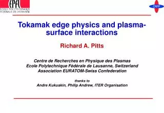
Tokamak edge physics and plasma-surface interactions. Richard A. Pitts Centre de Recherches en Physique des Plasmas Ecole Polytechnique Fédérale de Lausanne, Switzerland Association EURATOM-Swiss Confederation thanks to Andre Kukuskin, Philip Andrew, ITER Organisation.

E N D
Tokamak edge physics and plasma-surface interactions Richard A. Pitts Centre de Recherches en Physique des Plasmas Ecole Polytechnique Fédérale de Lausanne, Switzerland Association EURATOM-Swiss Confederation thanks toAndre Kukuskin, Philip Andrew, ITER Organisation
“Mission statement” for this talk … “The interaction of plasma with first wall surfaces will have a considerable impact on the performance of fusion plasmas, the lifetime of plasma-facing components and the retention of tritium in next step burning plasma experiments” Progress in the ITER Physics Basis, Chap. 4: “Power and particle control”, Nucl. Fusion 47 (2007) S203-S263 R. A. Pitts: Burning Plasma Diagnostics Workshop, Varenna, Italy, 24-28/09/2007
Outline • The scrape-off layer (SOL) and divertor • SOL power width • Divertor detachment • Plasma-surface interactions • Material lifetime – erosion and migration • Tritium retention • Dust • Mixed materials • What to diagnose …. CAVEAT: Edge plasma physics and PSI is a vast domain. Can only scratch the surface in this talk. Work referenced throughout the talk is listed at the end. R. A. Pitts: Burning Plasma Diagnostics Workshop, Varenna, Italy, 24-28/09/2007
Divertor and SOL physics R. A. Pitts: Burning Plasma Diagnostics Workshop, Varenna, Italy, 24-28/09/2007
Terminology: limiters and divertors C L Scrape-off layer (SOL) plasma: region of open field lines LCFS “Upstream” Core plasma Core plasma Outermidplane Separatrix Limiter X-point Private plasma Vessel walls Inner Outer Divertor targets R. A. Pitts: Burning Plasma Diagnostics Workshop, Varenna, Italy, 24-28/09/2007
Limiter and divertor phases in most JET shots • JET #62218, t = 3.0 s JET #62218, t = 15.2 s Limited Diverted Ramp-up and ramp-down phases in ITER will be in limited phase, ~30 s long [5]. Full burn divertor phase of ~400 s for the QDT = 10 inductive scenario R. A. Pitts: Burning Plasma Diagnostics Workshop, Varenna, Italy, 24-28/09/2007
Basics – SOL width, ln [1] lq, lT, ln B Main plasma SOL Limiter or divertor plate “upstream” WALL 2L “Connection length” • Any solid surface inserted into a plasma constitutes a very strong particle sink • In the high tokamak B-field:G << G|| • Thin Debye sheath (lD few 10’s mm thick ) forms at the surface controls flow of particles and energy || B Adapted from [1] • Quick and dirty estimate of ln with diffusive approx. for cross-field particle transport (all ionisation inside LCFS):G nv = -Ddn/dr ~ Dn/ ln v D/ln, ln= tvv|| cs ~ (kT/mi)1/2 Then, if t = t||, e.g. L ~ 30 m, TLCFS ~ 100 eV, cs ~ 105 ms-1, D~ 1 m2s-1 (near SOL) ln~ 1.7 cm!!cf. a = 2.0 m for ITEREven worse for energy – see next …… R. A. Pitts: Burning Plasma Diagnostics Workshop, Varenna, Italy, 24-28/09/2007
The problem with lq • SOL width for power, lq, is also small and is an important parameter of the edge plasma • As for particles, lq is determined by the ratio of to || transport (e.g. cross-field ion conduction and parallel electron conduction: ie (/||)1/2 ), where is anomalous • Scalings for lq can be derived from models and experiments, e.g.: • “2-point” analytic modelling:PSOL = power into SOL [1] • Scaling from H-mode experiments on JET [6]: • ITER modelling [7] assumes lq = 5 mm, JET scaling gives lq = 3.7 mm (cf. a=2.0 m) • Very recent multi-machine scaling [8] gives lq/R ~ constant • Note also that the parallel power flux, q|| PSOL/lq ~ as much as 1 GWm-2 in ITER Stored energy scales strongly with tokamak major radius, W ~ R4 [9]But power deposition area in the divertor Rlq only (~6 m2 in ITER) Bottom line is that despite its increased physical size, ITER will concentrate more power into a narrower channel at the plasma edge than today’s devices. The use of divertor detachment, radiation and geometry will be used to reduce the surface power flux densities to manageable levels, but careful monitoring will be critical see talk by Albrecht Herrmann. R. A. Pitts: Burning Plasma Diagnostics Workshop, Varenna, Italy, 24-28/09/2007
Power handling – ITER case (approx) lq = 5 mm ~100 MW q||,u ~ 500 MWm-2 • Max. steady-state power flux density permitted at ITER divertor targets: q 10 MWm-2 • Magnetic and divertor geometry alone cannot reduce the power to tolerable levels • Most of the parallel power flux must be prevented from reaching the plates divertor detachment and high radiative loss CORE PLASMA Magnetic flux expansion ~(Bq/B)u/(Bq/B)t ~4 for ITER outer divertor low field line angles at strike points (~3º)+ Target tilting in poloidal plane (a ~ 25º for ITER outer target) SOL a per target (adapted from [10]) q ~ 16 MWm-2 R. A. Pitts: Burning Plasma Diagnostics Workshop, Varenna, Italy, 24-28/09/2007
The route to detachment (1) Low n, high T (high PSOL)“Sheath limited” T n Target L u t n* rises as nu rises, finite electron heat conductivity: (note: k0,e» k0,i) allows parallel T gradients to develop Tt decreases, but pressure balance maintained (p|| ~ 0) so that nt rises strongly ( )lion ( 1/nt) decreases so that target recycling increases strongly flux amplificationAs Tt, radiation loss increases Tt further Moderate n, T“High recycling” T n Target Region of strong radiation losses L u t Mean free paths for particle collisions are long: SOL collisionality: is low Power flow to surface largely controlled by target sheath: g = sheath heat transmission coefficientepot = potential energy per incident ion R. A. Pitts: Burning Plasma Diagnostics Workshop, Varenna, Italy, 24-28/09/2007
The route to detachment (2) High n “Detached” Recycle region T Target n L u t At sufficiently low Tt, (< 5 eV), neutral ionisation rate < ion-neutral friction processes (CX, elastic scattering). Momentum transferred from ions to dense cloud of neutrals in front of the plate (recycle region) begins to reduce nt, p|| 0 and plasma pressure falls across recycle region.Once Tt ~1-2 eV (and if nt high enough), volume recombination locally “extinguishes” plasma, reducing target power flux Adapted from [2] Detachment seen experimentally in many devices, but complex “volumetric” process and relative importance of ion-momentum friction vs. recombination still unclear. X-point geometry long connection lengths high residence times in low Te plasma efficient radiative loss favouring power reductions where q|| is highest (i.e. on flux surfaces near separatrix). C-Mod, B. Labombard, et al., [11] R. A. Pitts: Burning Plasma Diagnostics Workshop, Varenna, Italy, 24-28/09/2007
Full detachment is a problem • Detachment which is too “strong” (particle flux reduced across the whole target) is often associated with zones of high radiation in the X-point region and confined plasma (MARFE) • MARFE formation can drive a transition from H to L-mode (H-mode density limit) or disruption • MARFE physics still not well modelled JET, A. Huber, et al. [12] Limit detachment to regions of highest power flux (where it is needed most).Maintain remainder of SOL in high recycling (attached)A few ways to arrange that this happens more readily: Divertor closure Target orientation Impurity seeding R. A. Pitts: Burning Plasma Diagnostics Workshop, Varenna, Italy, 24-28/09/2007
Divertor closure • Increased closure significantly improves divertor neutral pressure increased neutral density (nn), promoting earlier detachment • Closing “bypass” leaks important for increasing nn • Divertor closure also promotes helium compression and exhaust – very important for ITER and reactors Increasing closure JET, R. D. Monk, et al. [13] R. A. Pitts: Burning Plasma Diagnostics Workshop, Varenna, Italy, 24-28/09/2007
Target orientation Cooler, less dense plasma Separatrix Hotter plasma near separatrix AUG, A. Kallenbach, et al. [14] • Parallel heat fluxes significantly reduced for vertical cf. horizontal targets • Underlying effect is preferential reflection of recycled deuterium neutrals towards the separatrix Separatrix Increased ionisation near sep. Higher nt, lower Tt Higher CX losses Pressure loss, q|| R. A. Pitts: Burning Plasma Diagnostics Workshop, Varenna, Italy, 24-28/09/2007
Impurity seeding JET, G. F. Matthews et al. [16] DIII-D, C. J. Lasnier, et al. [15] Unfuelled D2 puff92 torrls-1 for 1.8 s Strong D2 puff Ne puff12 torrls-1 for 0.1 s Strong D2 +N2 puff Strong impurity seeding reduces ELM size but price is paid in confinement R. A. Pitts: Burning Plasma Diagnostics Workshop, Varenna, Italy, 24-28/09/2007
ITER divertor achieves partial detachment Inner strike pt. Outer strike pt. Power load (Wm-2) ITER Divertor DDD 17, Case 489 (SOLPS5 runs by A. Kukushkin) Deep V-shaped divertor, vertical, inclined targetsDome separating inner and outer targets – also helpful for diagnostics, neutron shielding and reducing neutral reflux to the core Kirschner et al. [17] R. A. Pitts: Burning Plasma Diagnostics Workshop, Varenna, Italy, 24-28/09/2007
Divertor exhaust e.g. ITER: He prod. rate ~21020s-1Max. divertor pumping speed ~200 Pa m3s-1~ 11023 He atom s-1 Cpump ~ 210-3 = 0.2%Typical acceptable He conc. in the core: ~4% hHe = 0.2/4 = 0.05 is minimum required. The values of and required for ITER have been achieved experimentally Apart from power handling, primary function of divertor is to deal with He from fusion reactions compress D, T, and He exhaust as much as possible for efficient pumping (and therefore also good density control). Critical criterion for an ITER burning plasma is that He is removed fast enough such that: is satisfied. is the global helium particle residence time – a function of tp, the He neutral density in the divertor and the pumping speed (conductance) [18]. Helium enrichment: is the ratio of He concentration in the divertor compared to the main plasma. To cryopumps R. A. Pitts: Burning Plasma Diagnostics Workshop, Varenna, Italy, 24-28/09/2007
Plasma-surface interaction R. A. Pitts: Burning Plasma Diagnostics Workshop, Varenna, Italy, 24-28/09/2007
ITER materials choices W CFC • Be for the first wall • Low T-retention • Low Z • Good oxygen getter • C for the targets • Low Z • Does not melt • Excellent radiator • W for the dome/baffles • High physical sputtering threshold Beryllium Driven by the need for operational flexibility • Possible alternative: • Be wall, all-W divertor To avoid problem of T-retention What are the issues associated with plasma-surface interactions? R. A. Pitts: Burning Plasma Diagnostics Workshop, Varenna, Italy, 24-28/09/2007
Critical issues Long term tritium retention Short and long range material migration Material mixing All strongly interlinked Steady state erosion Transient erosion(ELMs, disruptions) Material lifetime Redeposition R. A. Pitts: Burning Plasma Diagnostics Workshop, Varenna, Italy, 24-28/09/2007
Impurity migration Migration Erosion = Transport Deposition Re-erosion R. A. Pitts: Burning Plasma Diagnostics Workshop, Varenna, Italy, 24-28/09/2007
Erosion: Physical and chemical sputtering Physical Chemical (carbon) Adapted from Eckstein et al. [20] Roth et al. [21] ITER divertor flux D impact • No threshold • Dependent on bombarding energy, flux and surface temperature • Energy threshold higher for higher Z substrate • Much higher yields for high Z projectiles – important if using impurity seed gases Current steady state divertor target erosion rates (ERO modelling) due to Yphys and Ychem estimated at ~0.4 - 2 nms-1 for ITER [17] R. A. Pitts: Burning Plasma Diagnostics Workshop, Varenna, Italy, 24-28/09/2007
Erosion: transients, e.g. ELMs on the divertor Important factor is max. DTsurf due to arrival of short heat pulse (duration, t): f = fraction of Wth lost during transientAdiv, divertor wetted area (~6m2)r,k,C=density,conductivity,heat capacity ELM energy losses must stay below melting/sublimation/evaporation limit to avoid fast erosion (e.g. melt later loss) Important to measure Tmax Time (ms) Federici et al. [22] If Dtransient ~ few mm and target thickness ~ cm lifetime ~104 events~103 Type I ELMs/discharge lifetime ~ 10 ITER pulses!! This is the very lower limit for Type I ELMs observed today need to mitigate ELMs or find small ELM regimes and provide best possible monitoring of target erosion see talk by E. Gauthier (Thurs. morning)NB: plasma reattaches during ELMsand strong inherent ELM variability!! Tests on ITER target mock-ups with realistic energy fluxes show that damage threshold ~2x lower than for ideal materials (crack formation) [23,24] ELM energy flux 0.7 MJm-2 for W and CFC (~1.5% of Wth @ QDT = 10) R. A. Pitts: Burning Plasma Diagnostics Workshop, Varenna, Italy, 24-28/09/2007
Transport creates and moves impurities D0 from wall ion flux or gas puff CX event Ionisation Escape via divertor plasma Bypass leaks EDGE2D/NIMBUS Ions: Cross-field transport – turbulent driven ion fluxes can extend into far SOL recycled neutrals direct impurity releaseELMs can also reach first walls Eroded Impurity ions “leak” out of the divertor (Ti forces) SOL and divertor ion fluid flowscan entrain impurities Neutrals: • From divertor plasma leakage, gas puffs, bypass leaks low energy CX fluxes wall sputtering • Lower fluxes of energetic D0 from deeper in the core plasma • A problem for first mirrors see talk by Vladimir Voitsenya (Thurs. morning) Courtesy G.F. Matthews R. A. Pitts: Burning Plasma Diagnostics Workshop, Varenna, Italy, 24-28/09/2007
Migration balance – example from JET ~400g C • Make balance for period 1999-2001 with MarkIIGB divertor: 14 hours plasma in diverted phase (50400 s, 5748 shots) • Use spectroscopy and modelling to estimate main chamber sources • Post mortem surface analysis • Deposition almost all at inner divertor • Surface layers are Be rich C chemically eroded and migrates, Be stays put • Outer divertor – region of net erosion or balanced erosion/redeposition – BUT mostly attached conditions (not like ITER) 20gBe (BeII) 450gC (CIII) Main chamber: source of net erosion ~250 kg/year if JET operated full time!Carbon migrates to remote locations forming D-rich soft layers (high T-retention) 22g Be Strachan et al. [25] Likonen et al. [26]Coad et al. [27] R. A. Pitts: Burning Plasma Diagnostics Workshop, Varenna, Italy, 24-28/09/2007
Tritium retention (1) • One of the most challenging operational issues for burning plasmas • If carbon present, complex interplay between erosion hydrocarbons dissociation/ionisation transport re-deposition migration to remote areas with high sticking coefficients and retention in co-deposits • Carbon traps D, T very efficiently • D/C ratio can be in the range ~0.4 > 1 depending on the type of re-deposited layer • Retention very hard to characterise in today’s mostly carbon dominated devices • Dependent on materials, Tsurf, geometry (limiter/divertor), operating scenarios (H-mode, L-mode, low/high dens.) Reported measurements range from 3-50% retention [28]! e.g. on JET, ~3% obtained from long term, post mortem surface analysis, ~10-20% from gas balance R. A. Pitts: Burning Plasma Diagnostics Workshop, Varenna, Italy, 24-28/09/2007
Tritium retention (2) C targets, Tsurf = 800ºC, chemical+physical sputtering • A 400 s QDT = 10 ITER discharge will require ~50 g of T fuelling(cf. 0.01-0.2 g in today’s tokamaks) • Working guideline for max. in-vess. mobilisable T in ITER ~1kg[29,30] • World supply of T is also limited • Must avoid build-up in inaccessible locations • Predicting the expected retention in ITER is notoriously difficult ~2g/discharge ~0.02g/discharge Roth et al. [13]Kirschner et al. [30] ITER target [29] is a retention level of ~0.05 g/discharge ~7000 shots before major shutdown for T-removal • Very recent estimates (ERO code 2007 including Be main chamber influx) show that the in-vessel limit could be reached after only ~140 shots [17] • Modelling does not yet contain effects of transients (ELMs disruptions)! • No account taken for trapping in tile gaps Accurate measurement of T-retention and the development of efficient T-removal methods will be critical for the success of ITER R. A. Pitts: Burning Plasma Diagnostics Workshop, Varenna, Italy, 24-28/09/2007
Dust • Dust is seen in all tokamaks, especially with C walls • Not generally a concern in today’s devices … • But is potentially very important in ITER see talk by Sandrine Rosanvallon (Wednesday morning) • As an inventory for trapped tritium in areas difficult to access • As an explosive safety hasard – water leak hot surfaces steam hydrogen (by oxidation) possible explosion if enough air also present [31] • As a radiological or toxic hasard (activation products of W, tritium contained in Be, C dust, toxicity of Be dust) TCV:floor viewing IR camera during disruption, #33448 Carbon dust collected from tokamaks after operation periods is usually micron sized. Formed from flaking and degradation of deposited films, unipolar arcing, brittle fracture (e.g. due to transients) etc. No real idea yet how much dust ITER will generate, where it will go or how to get it out a big effort needed to improve this situation DIII-D:floor viewing DiMES TV with near IR filter. 2nd shot in 2007 after “dirty vent”, #127331. Courtesy of D. L. Rudakov & W. P. West [32] R. A. Pitts: Burning Plasma Diagnostics Workshop, Varenna, Italy, 24-28/09/2007
Mixed Materials No fusion device operating today contains the material mix currently planned for the ITER first wall and divertor: Be, W, C. Cross contamination of the material surfaces will be unavoidable. This is likely to have several consequences [29]: • Formation of metallic carbides diffusion of C into bulk material at high temperatures • Formation of Be-W alloys melting point can be reduced by as much as ~2000ºC Material property changes due to mixing • Retention of H in BeO can be as high as in C • Retention in W can be increased by C or oxide layers but is very low in pure W or Be • Very complex – difficult to predict yet for ITER Effect on H-isotope retention • Can both increase and decrease erosion! • Heavy ions (e.g. BeZ+, CZ+) on C, W increased phys. sputt. but surface coverage (e.g. Be on C) reduces chemical sputtering. Effect on material erosion Preparations underway at JET to test a Be/W & Be/W/C wall mix from ~2010 [33] R. A. Pitts: Burning Plasma Diagnostics Workshop, Varenna, Italy, 24-28/09/2007
So, what needs to be diagnosed [34]? Courtesy of A. Kukushkin Te ne Prad Wall temperature and visible imageMain chamber gas pressure and gas compositionSOL neutral density (D/T)Impurity influxesSOL ne, Te profiles (but challenging) ne, Te, Prad, position of ionisation front, nHe, nD/nT, impurity and D, T influxes Cryopump inlet composition (H/D/T/He, CxHy) Target plate heat and particle fluxes, Te, surface temperature, erosion rate Neutral gas pressure Dust accumulation? See next talk by Philip Andrew! R. A. Pitts: Burning Plasma Diagnostics Workshop, Varenna, Italy, 24-28/09/2007
References (1) A 45 min. talk can only hope to scratch the surface of such a vast field. Some good reference sources covering aspects of the material in this talk are the following: [1]“The plasma boundary of magnetic fusion devices”, P. C. Stangeby, IoP Publishing Ltd, Bristol, 2000 [2] “Experimental divertor physics”, C. S. Pitcher and P. C. Stangeby, Plasma Phys. Control. Fusion 39 (1997) 779 [3] “Plasma-material interactions in current tokamaks and their implications for next step fusion reactors”, G. Federici et al., Nucl. Fusion 39 (1997) 79 [4] “Material erosion and migration in tokamaks”, R. A. Pitts et al., Plasma Phys. Control. Fusion 47 (205) B303 A number of additional papers have been used to prepare the slides in this presentation. They are listed below in order of appearance in the talk. [5]“Simulations of ITER start-up and assessment of initial power loads”, G. Federici et al., J. Nucl. Mater. 363-365 (2007) 346 [6] “Boundary plasma energy transport in JET ELMy H-modes”, W. Fundamenski and W. Sailer, Nucl. Fusion 44 (2003) 20 [7] “Scaling laws for edge plasma parameters in ITER from two-dimensional edge modelling”, A. Kukushkin et al., Nucl. Fusion 43 (2003) 716 [8] “Plasma-surface interaction, scrape-off layer and divertor physics: implications for ITER”, B. Lipschultz et al., Nucl. Fusion 47 (2007) 1189 [9] “Steady state and transient power handling in JET”, G. F. Matthews et al., Nucl. Fusion 43 (2003) 999 [10] “The plasma-wall interaction region: a key low temperature plasma for controlled fusion”, G. F. Counsell, Plasma Sources Sci. Technol. 11 (2002) A80 [11]“Experimental investigation of transport phenomena in the scrape-off layer and divertor”, B. LaBombard et al., J. Nucl. Mater. 241-243 (1997) 149 [12]“Improved radiation measurements on JET – first results from an upgraded bolometer system”, A. Huber et al., J. Nucl. Mater. 363-365 (2007) 365 [13] “Recent results from divertor and scrape-off layer studies on JET”, R. D. Monk et al., Nucl. Fusion 39 (1999) 1751 [14] “Scrape-off layer radiation and heat load to the ASDEX Upgrade LYRA divertor”, A. Kallenbach et al., Nucl. Fusion 39 (1999) 901 R. A. Pitts: Burning Plasma Diagnostics Workshop, Varenna, Italy, 24-28/09/2007
References (2) [15] “Study of target plate heat load in diverted DIII-D tokamak discharges”, C. Lasnier et al., Nucl. Fusion 38 (1998) 1225 [16] “Studies in JET divertors of varied geometry: II Impurity seeded plasmas”, G. F. Matthews et al., Nucl. Fusion 39 (1999) 19 [17]“Modelling of tritium retention and target lifetime of the ITER divertor using the ERO code”, A. Kirschner et al., J. Nucl. Mater. 363-365 (2007) 91 [18] “ITER Physics basis: Chapter 4, power and particle control”, Nucl. Fusion 39 (1999) 2391 [19] “Material migration in JET”, G. F. Matthews et al., Proc. 30th EPS Conf. on Control. Fusion and Plasma Physics (St. Petersburg, 2003) 27A (ECA) P-3.198 [20]W. Eckstein et al., IPP Garching report number 9/82 (1993) [21] “Flux dependence of carbon chemical erosion by deuterium ions”, J. Roth et al., Nucl. Fusion 44 (2004) L21 [22] “Assessment of the erosion of the ITER divertor targets during Type I ELMs”, G. Federici et al., Plasma Phys. Control. Fusion 45 (2003) 1523 [23] “Transient energy fluxes in tokamaks : Physical processes and consequences for next step devices”, A. Loarte et al., 34th EPS Conf. on Control. Fusion and Plasma Physics (Warsaw, 2007) [24]“Effect of ELMs on ITER divertor armour materials”, A. Zhitlukhin et al., J. Nucl. Mater. 363-365 (2007) 301 [25] “JET carbon screening experiments using methane gas puffing and its relation to intrinsic carbon impurities”, J. D. Strachan et al., Nucl. Fusion 43 (2003) 922 [26]“Beryllium accumulation at the inner divertor of JET”, J. Likonen et al., J. Nucl. Mater. 337-339 (2005) 60 [28]“Gas balance and fuel retention in fusion devices”, T. Loarer et al., Nucl. Fusion 47 (2007) 1112 [29] “Progress in the ITER Physics basis: Chapter 4: Power and particle control”, Nucl. Fusion 47 (2007) S203 [30] “ITER Technical Basis”, ITER EDA Documentation Series No. 24 (Vienna: IAEA) 2002 [31] “The safety implications of tokamak dust size and surface area”, K. A. McCarthy et al., Fus. Eng. Design 42 (1998) 45 [32] “Observations of Dust in DIII-D Divertor and SOL”, D. L. Rudakov et al., 1st Workshop on “Dust in Fusion Plasmas”, 8-10 July 2007, Warsaw, Poland [33] “An ITER-like wall for JET”, J. Pamela et al., J. Nucl. Mater. 363-365 (2007) 1 [34] “Progress in the ITER Physics basis: Chapter 7: Diagnostics”, Nucl. Fusion 47 (2007) S337 R. A. Pitts: Burning Plasma Diagnostics Workshop, Varenna, Italy, 24-28/09/2007