Chapter 11: Internet Operation
Chapter 11: Internet Operation. Business Data Communications, 7e. Objectives. Internet Addressing Internet Routing Protocols The Need for Speed and Quality of service Differentiated Services. Internet Addressing.

Chapter 11: Internet Operation
E N D
Presentation Transcript
Chapter 11:Internet Operation Business Data Communications, 7e
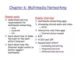
Objectives • Internet Addressing • Internet Routing Protocols • The Need for Speed and Quality of service • Differentiated Services
Internet Addressing • 32-bit global internet address for source & destination in the IP header (base on IPv4) • Includes a network identifier and a host identifier • Dotted decimal notation • 11000000 11100100 00010001 00111001 (binary) • 192.228.17.57 (decimal)
Class-Based IP Addresses • Rightmost bits of the 32-bit IP address designate a host • The leftmost bits of the 32-bit address designate a network • Class-based, or classful, IP addressing was adopted to allow for a variable allocation of bits to specify network and host • The first few leftmost bits specify how the rest of the address should be separated into network and host fields • This provides flexibility in assigning addresses to hosts and allows a mix of network sizes on an internet
Network Classes • Class A:Few networks, each with many hostsAll addresses begin with binary 0 • Class B: Medium networks, medium hostsAll addresses begin with binary 10 • Class C: Many networks, each with few hosts All addresses begin with binary 110
Network Classes (cont.) • IP addresses are usually written in: “Dotted Decimal Notation”, i.e. a decimal number represent each byte of the 32-bit address. • Example:Binary representation of an IP is : 11000000111001000001000100111001Decimal representation is: 192.228.17.57 (decimal).
Network Classes (cont.) • Class A Network begins with 0 • Note: Network addresses (0000 0000) and (0111 1111) are reserved Therefore Class A contains: (27 - 2 = 128 - 2 = 126) network numbers • Range of the 1st decimal number for Class A:1.***.***.*** to 127.***.***.***
Class B Network Classes (cont.) • Class B begin with binary 10starts from 1000 0000 (128)ends to 1011 1111 (191)i.e. Range of the 1st decimal number for Class B:128.***.***.*** to 191.***.***.***the 2nd Byte is also part of class Bi.e. there are 214 = 16,384 Class B addresses
Network Classes (cont.) • Class C begin with binary 110starts from 11000000 (192)ends to 11011111 (223)Range of the 1st decimal number for class C:192.***.***.*** to 223.***.***.*** the 2nd & 3rd Byte is also part of class CThere are 221 = 2,097,152 Class C addresses
Subnets & Subnet Masks • Allows for subdivision of internets within an organization andadd a number of LANs to the internet and insulate their internal complexity within their organization by assigning a single“networknumber” to all the LANs • Each LAN can have a subnet number, allowing routing among networks • Host portion is partitioned into subnet and host numbers • From the point of view of the rest of the internet, there is a single network at that site. • This simplifies addressing and routing.
Subnets & Subnet Masks (Cont.) • Then to allow the Routers within the site to function properly, each LAN is assigned a subnet number. 32-bitSourceAddress 32-bitSourceAddress
Subnets & Subnet Masks (Cont.) • To include the subnet number, the host portion of the internet address is partitioned into a subnet number and a host number to accommodate this new level of addressing. Network Portion: Class A: 7 + 1bits Class B: 14+2 bits Class C: 21+ 3 bits Host Portion: Class A: 24bit Class B: 16 bit Class C: 8 bit Network Host Extended Network Number or Address Mask: Within the subnetted network, the local Routers must route on the basis of an extended network number Subnet Host Network
Subnets & Subnet Masks (Cont.) • The use of address mask allows the host to determine whether an outgoing datagram is destined for a host on the same LAN (send directly) or another LAN (send datagram to router) • Some methods (manual config.) are used to create address masks and make them known to the local routers
Subnets & Subnet Masks (Cont.) The effect of the subnet mask is to erase the portion of the host field that refers to an actual host on a subnet. What remains is the network number and the subnet number.
Subnets & Subnet Masks (Cont.) A local complex consisting of 3 LANs and 2 Routers.To the rest of the internet, this complex is a single network with a class C address of the form 192.228.17.X, where 192(1100 0000) is the network number andxthehostnumber. Example of Subnetworking:
Subnets & Subnet Masks (Cont.) Net ID/subnet ID:192.228.17.32 Subnet number:1 IP Address:192.228.17.33 Host number:1 IP Address:192.228.17.57 Host number:25 Net ID/subnet ID :192.228.17.64 Subnet number:2 IP Address:192.228.17.65 Host number:1 Net ID/subnet ID :192.228.17.96 Subnet number:3 IP Address:192.228.17.97 Host number:1 • Example1: A datagram with the destination address 192.228.17.57 arrives at R1 from the rest of the internet or from LAN Y. R1 has addresses of LAN X, LAN Y, LAN Z. R1 doesn’t know about hosts internal to these LANs. • In order to determine where R1 should send the datagram with receiver address 192.228.17.57. R1 bitwise AND the subnet mask: (1111 1111.1111 1111.1111 1111.1110 000) i.e. (255.255.255.224) and IP address (192.228.17.57) to determine that destination address 192.228.17.57 refers to subnet: (11000000.111.00100.00010001.001) i.e. 1, which is LAN X, and so forward the datagram to LAN X. For both R1 & R2 Routers The effect of the subnet mask is to erase the portion of the host field that refers to an actual host on a subnet. What remains is the network number and the subnet number.
Subnets & Subnet Masks (Cont.) Net ID/subnet ID:192.228.17.32 Subnet number:1 IP Address:192.228.17.33 Host number:1 IP Address:192.228.17.57 Host number:25 Net ID/subnet ID :192.228.17.64 Subnet number:2 IP Address:192.228.17.65 Host number:1 Net ID/subnet ID :192.228.17.96 Subnet number:3 IP Address:192.228.17.97 Host number:1 • Example2: If a datagram with destination address (192.228.17.57) arrives at R2 from LAN Z, R2 applies the mask and then determines from its forwarding database that datagrams destined for subnet 1 should be forwarded to R1 • Hosts must also employ a subnet mask to make routing decisions. • The default subnet mask for a give class of addresses is a null mask, which yields the same network and host number as the non-subnetted address.
Classless Inter-Domain Routing (CIDR) • Makes more efficient use of the 32-bit IP address than the class-based method • Does away with the class designation and with the use of leading bits to identify a class • Each 32-bit address consists of a leftmost network part and a rightmost host part, with all 32 bits used for addressing • Associated with each IP address is a prefix value that indicates the length of the network portion of the address • A CIDR IP address is written as a.b.c.d/p • a is the value of the first byte of the address • b the value of the second byte • c the value of the third byte • d the value of the fourth byte • p is in the range of 1 through 32 and indicates the length of the network portion of the address Examples: Class B Network with an implied network mask 255.255.0.0 is defined as 172.16.0.0/16 16 bits 1 and 16 bits 0 Class C Network with 192.168.99.0/24 24 bits 1 and 8 bits 0 Supernetting: Multiple IP addresses referring to a block of CIDR addresses can be identified with a single mask.
IPv6 Addresses IPv6 addresses are 128 bits in length. Addresses are assigned to individual interfaces on nodes, not to the nodes themselves. A single interface may have multiple unique unicast addresses. Any of the unicast addresses associated with a node’s interface may be used to uniquely identify that node. As with IPv4, IPv6 addresses use CIDR rather than address classes. Anycast Address
Internet Routing Protocols • Routers are responsible for receiving and forwarding packets between interconnected networks • Routers make decisions based on the knowledge of the topology and traffic/delay conditions of the Internet. (based on topology leads to a static -permanent- route based on the traffic makes it a dynamic route) • Must dynamically adapt to changing network conditions to avoid congested and failed portions of the network. • Two key concepts to distinguish in routing function: • Routing information RI: Information about topology & delays • Routing algorithm: The algorithm used to make a routing decision for a particular datagram, based on the current RI
Autonomous Systems (AS) To proceed with Routing Protocol let’s introduce AS: • Key characteristics of an AS • Set of routers and networks managed by a single organization • Set of routers exchanging information via a common routing protocol • Connected (in a graph-theoretic sense); that is, there is a path between any pair of nodes (except in times of failure). • Interior Router Protocol (IRP) passes information between routers within an AS • Exterior Router Protocol (ERP) passes information between routers in differentASs • The protocol used within the AS does not need to be implemented outside of the system • This flexibility allows IRPs to be custom tailored to specific applications and requirements
Interior router Protocol Exterior router protocol Application of Interior and Exterior Routing Protocols Autonomous System 1 Autonomous System 2
IRP & ERP • IRP: Interior router protocol • Needs to build up a detailed model of the interconnection of routers within an AS in order to calculate the least-cost path from a given router to any network within the AS • ERP: Exterior router protocol • Supports the exchange of summary reachability information between separately administered ASs. Use of summary information means that an ERP is simpler and uses less detailed information than an IRP
Border Grouping Protocol (BGP) • BGP was designed to allow routers (called gateways) in different AS to cooperate in the exchange of routing information. • BGP has become the preferred ERP(Exterior Router Protocol) for the internets that employ TCP/IP suite. • BGP has 3 functional procedures: 1. Neighbor acquisition 2. Neighbor reachability 3. Network reachability
Open Shortest Path First (OSPF) • Widely used as IRP(Interior Router Protocol) in TCP/IP networks • Uses link state routing algorithm • Routers maintain topology database of AS • Topology is express as directed graph consisting of: Router Network Carry data that neither originates nor terminates on an end system attached to this network Vertices or Nodes: Transit: Stub: If it is not a transit network Connecting router vertices of two router connected by point-to-point link. Connecting router vertex to network vertex of directly connected. Edges
Directed Graph of the Autonomous System An Autonomous System Open Shortest Path First (OSPF)Cnt’d
Open Shortest Path First (OSPF)Cnt’d Directed Graph of the Autonomous System SPF tree for R6 An Autonomous System
Routing Table for R6 SPF tree & Routing Table for Router R6 SPF tree for R6
Multicasting • Sending a packet from a source to the members of a multicast group • Multicast addresses • Addresses that refer to a group of hosts on one or more networks • Practical applications include: • Multimedia • Teleconferencing • Database • Distributed computation • Real-time workgroup
Multicast Routing Protocols • At the local level, individual hosts need a method of joining or leaving a multicast group • Internet Group Management Protocol (IGMP) • Used between hosts and routers on a broadcast network such as Ethernet or a wireless LAN to exchange multicast group membership information • Supports two principal operations: • Hosts send messages to routers to subscribe to and unsubscribe from a multicast group defined by a given multicast address • Routers periodically check which multicast groups are of interest to which hosts
Interior Routing Protocols • Routers must cooperate across an organization’s internet or across the Internet to route and deliver multicast IP packets • Routers need to know which networks include members of a given multicast group • Routers need sufficient information to calculate the shortest path to each network containing group members • Multicast Extensions to OSPF(open shortest path first)(MOSPF) • Enhancement to OSPF for the exchange of multicast routing information • Protocol Independent Multicast (PIM) • Designed to extract needed routing information from any unicast routing protocol and may support routing protocols that operate across multiple ASs with a number of different unicast routing protocols
The need for speed and QoS The Emergence of High-Speed LANs • Role of PCs & requirements of LANs in need for High-speed: • More powerful PCs, graphical applications & GUI • -MIS Recognition of LAN as a viable computing platform, -C/S computing in business, -Graphics in transaction, -interactive applications on the Internet, -need to reduce the acceptable delay on data transfer creating large volume of data to be handled over LANs. So that 10Mbps Ethernets and 16 Mbps token rings are not adequate for High-speed LANs. • Effect has been to increase volume of traffic over LANs: • Examples of requirements calling for high speed LAN • Centralized server farm (e.g. color publishing operation) • Power workgroup (e.g. software developers, CAD users transferring huge files across the Internet to share with piers.) • High-speed local backbone (i.e. interconnection of these LANs) • Convergence and unified communications (voice/video, and collaborative applications have increased the LAN traffic)
The need for speed and QoS • Corporate Wide Area Networking • Greater dispersal of employee base • Changing application structures • Increased client/server and intranet • Wide deployment of GUIs • Dependence on Internet access • More data must be transported off premises and into the wide area • Digital Electronics • Major contributors to increased image and video traffic • Digital Versatile Disc (DVD) • Increased storage means more information to transmit • Digital Still Camera • Camcorders • Still Image Cameras
Quality of Service (QoS) • Real-time voice and video don’t work well under the Internet’s “best effort” delivery service • Best effort? • fair delivery service, internet treats all packets equally. During congestion packet delivery slows down. In severe congestions, packets are dropped at random to ease congestion. No distinction is made in terms of the relative importance or timeliness of traffic/packets. (ATM)-”Asynchronous Transfer Mode”, a packet switching with fix size cells of 53 octet • QoS provides for varying application needs in Internet transmission
Categories of Traffic • Elastic • Can adjust to changes in delay and throughput access • Examples: File transfer, e-mail, web access • Inelastic • Does not adapt well, if at all, to changes • Examples: Real-time voice, audio and video
Inelastic Traffic Requirements • Throughput • Requires a firm minimum value for throughput • Delay • result in acting late to disadvantage (e.g. stock trading) • Delay Variation • RT applications (e.g. teleconferencing) require an upper bound. As the allowable delay gets larger, real delay in delivering the data gets longer and a larger delay buffer is required at the receivers • Packet loss • RT applications can sustain packet loss with varying amount
Requirements of Inelastic Applications • 1. Application need to state their requirements either: • In advance by service request • on the fly by means of fields in the IP • The 1st approach is preferred because the network can anticipate demands and deny new requests if the resources are limited. • 2. During congestion, elastic traffic need still be supported by: • introducing a reservation protocol to deny service requests that would leave too few resources available to handle current elastic traffic
A Comparison of Application Delay Sensitivity and Criticality in an Enterprise Sensitivity ==> demand Qos to provide TIMELY and HIGH data rate Criticality ==> QoS to provide RELIABILITY
Differentiated Services (DS) • Provide QoS on the basis of the needs of different groups of users • Most widely accepted QoS mechanism in enterprise networks • Key characteristics: • No change is required to IP • Existing applications need not be modified to use DS • Provides a built-in aggregation mechanism – all traffic with the same DS octet is treated the same by the network service • Routers deal with each packet individually and do not have to save state information on packet flows
Differentiated Services (DS) • Functionality in the internet and private internets to support specific QoS requirements for a group of users, all of whom use the same service label in IP packets. • All the traffic on the Internet is split into groups with different QoS requirements and that routers recognize different groups on the basis of a label in the IP header.
Differentiated Services (DS)-Cont. • Provides QoS based on “user groupneeds” rather than traffic flows • Key characteristics of DS: • Differing QoS are labeled using the “6-bit DS field” in the IPv4 and IPv6 headers • Service-Level Agreements (SLA) govern DS, eliminating need for application-based assignment • DS provides a built-in aggregation mechanism. All traffic with the same DS octet is treated the same by the network service • DS is implemented in individual router by queuing and forwarding packets based on the DS octet