Learning Objectives :
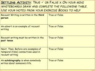
Learning Objectives :. Understand the need for dimensioning in drawings. Understand the fundamental dimensioning terms . Understand associative dimensioning . Use the QDIM command for quick dimensioning. Create various types of dimensions in the drawing.

Learning Objectives :
E N D
Presentation Transcript
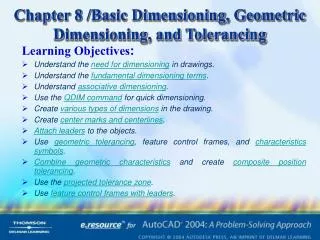
Learning Objectives: • Understand the need for dimensioning in drawings. • Understand the fundamental dimensioning terms. • Understand associative dimensioning. • Use the QDIM command for quick dimensioning. • Create various types of dimensions in the drawing. • Create center marks and centerlines. • Attach leaders to the objects. • Use geometric tolerancing, feature control frames, and characteristics symbols. • Combine geometric characteristics and create composite position tolerancing. • Use the projected tolerance zone. • Use feature control frames with leaders.
DIMENSIONING IN AutoCAD The objects that can be dimensioned in AutoCAD range from straight lines to arcs. The dimensioning commands provided by AutoCAD can be classified into four categories: Dimension Drawing Commands Dimension Style Commands Dimension Editing Commands Dimension Utility Commands While dimensioning an object, AutoCAD automatically calculates the length of the object or the distance between two specified points. Also, settings such as a gap between the dimension text and the dimension line, the space between two consecutive dimension lines, arrow size, and text size are maintained and used when the dimensions are being generated for a particular drawing. Learning Objectives
FUNDAMENTAL DIMENSIONING TERMS Before studying AutoCAD’s dimensioning commands, it is important to know and understand various dimensioning terms that are common to linear, angular, radius, diameter, and ordinate dimensioning. The following figures show various dimensioning parameters. Various dimension parameters Various dimension parameters Learning Objectives
The various dimensioning terms that are commonly used are: Dimension Line Dimension Text Arrowheads Extension Lines Leader Center Mark and Centerlines Alternate Units Tolerances Limits Learning Objectives
Dimension Line The dimension line indicates which distance or angle is being measured. Usually this line has arrows at both ends, and the dimension text is placed along the dimension line. By default the dimension line is drawn between the extension lines. Dimension Text Dimension text is a text string that reflects the actual measurement (dimension value) between the selected points as calculated by AutoCAD. Arrowheads AutoCAD allows you to draw arrows, tick marks, closed arrows, open arrows, dots, right angle arrows, or user-defined blocks as shown in the figure. Using arrows, tick marks, and user-defined blocks Learning Objectives Dimensioning Terms
Extension Lines Extension lines are drawn from the object measured to the dimension line. These lines are also called witness lines. Extension lines are used in linear and angular dimensioning. Generally, extension lines are drawn perpendicular to the dimension line. However, you can make extension lines incline at an angle by using the DIMEDIT command. AutoCAD also allows you to suppress either one or both extension lines in a dimension. Extension lines Extension line suppression Learning Objectives Dimensioning Terms
Leader A leaderis a line that stretches from the dimension text to the object being dimensioned. For example, the circle as shown in the figure has a keyway slot that is too small to be dimensioned. In this situation, a leader can be drawn from the text to the keyway feature. Also, a leader can be used to attach annotations such as part numbers, notes, and instructions to an object. Leader used to attach annotation Learning Objectives Dimensioning Terms
Center Mark and Centerlines The center mark is a cross mark that identifies the center point of a circle or an arc. Centerlines are mutually perpendicular lines passing through the center of the circle/arc and intersecting the circumference of the circle/arc. A center mark or the centerlines are automatically drawn when you dimension a circle or arc. The length of the center mark and the extension of the centerline beyond the circumference of the circle is determined by the value assigned to the DIMCEN dimension variable Center mark and centerlines Learning Objectives Dimensioning Terms
Alternate Units With the help of alternate unitsyou can generate dimensions for two systems of measurement at the same time as shown in the figure. For example, if the dimensions are in inches, you can use the alternate units dimensioning facility to append metric dimensions to the dimensions Using alternate units dimensioning Learning Objectives Dimensioning Terms
Tolerances Tolerance is the amount by which the actual dimension can vary. AutoCAD can attach the plus/minus tolerances to the dimension text (actual measurement computed by AutoCAD). This is also known as deviation tolerance. Using tolerances with dimensions Learning Objectives Dimensioning Terms
Limits Instead of appending the tolerances to the dimension text, you can apply the tolerances to the measurement itself. Once you define the tolerances, AutoCAD will automatically calculate the upper and lower limitsof the dimension. These values are then displayed as a dimension text. For example, if the actual dimension as computed by AutoCAD is 2.6105 units and the tolerance values are +0.025 and -0.015, the upper and lower limits are 2.6355 and 2.5955. After calculating the limits, AutoCAD will display them as dimension text, as shown in figure. Using limits dimensioning Learning Objectives Dimensioning Terms
ASSOCIATIVE DIMENSIONS Associative dimensioning is a method of dimensioning in which the dimension is associated with the object that is dimensioned. In other words, the dimension is influenced by the changes in the size of the object. In the previous releases of AutoCAD, the dimensions were not truly associative, but were related to the objects being dimensioned by definition points on the DEFPOINTS layer. The associative dimensions automatically update their values and location if the value or location of the object is modified. For example, if you edit an object using simple editing operations such as breaking using the BREAK command, then the true associative dimension will be modified automatically. The dimensioning variable DIMASSOC controls associativity of dimensions. The default value of this variable is 1, which means turned on. Learning Objectives
DEFINITION POINTS Definition points are the points drawn at the positions used to generate a dimension object. The definition points are used by the dimensions to control their updating and rescaling. AutoCAD draws these points on a special layer calledDEFPOINTS. These points are not plotted by the plotter because AutoCAD does not plot any object on the DEFPOINTS layer. Definition points of linear, angular, and ordinate dimensions Learning Objectives
SELECTING DIMENSIONING COMMANDS The various methods of selecting dimension commands are: Using the Toolbar and the Dimension Menu Using the Command Line Learning Objectives
Using the Toolbar and the Dimension Menu You can select the dimension commands from the Dimension toolbar by choosing the desired dimension button, or from theDimension menu. The Dimensiontoolbar can also be displayed by right-clicking on anytoolbar and choosing Dimensionsfrom the shortcut menu. Selecting dimensions from the Dimension menu SELECTING DIMENSIONING COMMANDS Learning Objectives Dimension toolbar
Using the Command Line You can directly enter a dimensioning commandin the Command line or use the DIM or the DIM1 commands to invoke the dimensioning commands. SELECTING DIMENSIONING COMMANDS Learning Objectives
Using Dimensioning Commands The first method of using the Command line is to directly enter the dimensioning command in the Command line. For example, if you want to draw the linear dimension, the DIMLINEAR command can be entered directly at the Command prompt. DIM and DIM1 Commands Since dimensioning has several options, it also has its own command mode. The DIMcommand keeps you in the dimension mode, and the Dim:prompt is repeated after each dimensioning command until you exit the dimension mode to return to the normal AutoCAD Command prompt. The DIM1command is similar to the DIMcommand. The only difference is that DIM1 lets you execute a single dimension command and then automatically takes you back to the normal Command prompt. COMMAND LINE Learning Objectives
AutoCAD has provided the following six fundamental dimensioning types: Quick dimensioningLinear dimensioningAngular dimensioning Diameter dimensioningRadius dimensioningOrdinate dimensioning Linear and angular dimensions Radius, diameter, and ordinate dimensions Learning Objectives
DIMENSIONING NUMBER OF OBJECTS TOGETHER The QDIM command allows you to dimension a number of objects at the same time. It also allows you to quickly edit dimension arrangements already existing in the drawing and also create new dimension arrangements. It is especially useful when creating a series of baseline or continuous dimensions. It also allows you to dimension multiple arcs and circles at the same time. When you are using the QDIM command, you can relocate the datum base point for baseline and ordinate dimensions. Using the QDIM command to quickly dimension multiple circles FUNDAMENTAL DIMENSIONING Learning Objectives
CREATING LINEAR DIMENSIONS Linear dimensioningapplies to those dimensioning commands that measure the shortest distance between two points. You can directly select the object to dimension or select two points. In case the object selected is aligned then the linear dimensions will add Horizontal or Vertical dimensions to the object. Instead of selecting the object, you can also select the two endpoints of the line that you want to dimension as shown in the figure. Drawing linear dimension FUNDAMENTAL DIMENSIONING Learning Objectives
DIMLINEAR Command Options The options provided under this command are discussed next. Mtext Option The Mtext option allows you to override the default dimension text and also change the font, height, and so on, using the Multiline Text Editordialog box. By default, it includes the <> code to represent the measured dimension text. Text Option This option also allows you to override the default dimension. However, this option will prompt you to specify the new text value in the Command prompt itself, see figure. Text, Angle, Horizontal, Vertical, and Rotated options Learning Objectives
Horizontal Option Angle Option This option lets you change the angle of the dimension text. This option lets you create a horizontal dimension regardless of where you specify the dimension location. Vertical Option This option lets you create a vertical dimension regardless of where you specify the dimension location. Rotated Option This option lets you create a dimension that is rotated at a specified angle. COMMAND OPTIONS Learning Objectives
Example 1 In this example, you will use the linear dimensioning to dimension a horizontal line of 4 units length. The dimensioning will be done by selecting the object and by specifying the first and second extension line origins. Using the Multiline Text Editor modify the default text such that the dimension is underlined. Selecting the Object • Choose the Linear Dimensionbutton from the Dimensiontoolbar. The prompt sequence is as follows: Specify first extension line origin or <select object>:« Select object to dimension:Select the line. Specify dimension line location or [Mtext/Text/Angle/Horizontal/Vertical/Rotated]: M Learning Objectives
The Multiline Text Editor will be displayed as shown in the figure. The default dimension value will be displayed in the <> code. Select this code and then choose the Underline button to underline the text. Specify dimension line location or [Mtext/Text/Angle/Horizontal/Vertical/Rotated]: Place the dimension. Dimension text = 4.00 Multiline Text Editor dialog box Learning Objectives Example 1
Specifying Extension Line Origins • Choose the Linear Dimensionbutton from the Dimensiontoolbar. The prompt sequence is as follows: Specify first extension line origin or <select object>: Select the first endpoint of the line using the Endpoint object snap. Specify second extension line origin: Select the second endpoint of the line using the Endpoint object snap. Specify dimension line location or [Mtext/Text/Angle/Horizontal/Vertical/Rotated]:M Select the code and then choose the Underline button . Specify dimension line location or [Mtext/Text/Angle/Horizontal/Vertical/Rotated]:Place the dimension. Dimension text = 4.00 Line for Example 1 Learning Objectives Example 1
CREATING ALIGNED DIMENSIONS Generally, the drawing consists of various objects that are neither parallel to the X axis nor to the Y axis. Dimensioning of such objects can be done using the aligned dimensioning. With the help of aligned dimensioning, you can measure the true aligned distance between the two points. The dimension created with the ALIGNEDcommand is parallel to the object being dimensioned. Aligned dimensioning Learning Objectives
Exercise 1 Draw the object shown in figure and then use linear and aligned dimensioning to dimension the part. The distance between the dotted lines is 0.5 units. The dimensions should be up to 2 decimal places. To get dimensions up to 2 decimal places, enter DIMDEC at the Command prompt and then enter 2. Drawing for Exercise 1 Learning Objectives
CREATING ROTATED DIMENSIONS Rotated dimensioning is used when you want to place the dimension line at an angle (if you do not want to align the dimension line with the extension line origins selected). The ROTATED dimension option will prompt you to specify the dimension line angle. You can invoke this command by using DIMLINEAR(Rotate option) or by entering ROTATED at the Dim: Command prompt. Rotated dimensioning Learning Objectives
CREATING BASELINE DIMENSIONS With this command you can continue a linear dimension from the first extension line origin of the first dimension. The new dimension line is automatically offset by a fixed amount to avoid overlapping of the dimension lines. This has to be kept in mind that there must already exist a linear, ordinate, or angular associative dimension to use the Baseline dimensions. Baseline dimensioning Learning Objectives
CREATING CONTINUED DIMENSIONS With this command you can continue a linear dimension from the second extension line of the previous dimension. This is also called as chainedorincremental dimensioning. There must existlinear, ordinate, or angular associative dimension to use the Continue dimensions. Continue dimensioning Learning Objectives
Exercise 2 Draw the object as shown in the figure. Then use thebaselinedimensioning to dimension the top half and continue dimensioningto dimension the bottom half. The distance between the dotted lines is 0.5 units. Drawing for Exercise 2 Learning Objectives
CREATING ANGULAR DIMENSIONS Angulardimensioning is used when you want to dimension an angle. This command generates a dimension arc (dimension line in the shape of an arc with arrowheads at both ends) to indicate the angle between two nonparallel lines. For every set of points there exists one acute angle and one obtuse angle (inner and outer angles). If you specify the dimension arc location between the two points, you will get the acute angle; if you specify it outside the two points, you will get the obtuse angle. Angular dimensioning between two nonparallel lines FUNDAMENTAL DIMENSIONING Learning Objectives
The methods of dimensioning various entities using Angular Dimensioning command are: Dimensioning the Angle Between Two Nonparallel Lines Dimensioning the Angle of an Arc Angular Dimensioning of Circles Angular Dimensioning Based on Three points Learning Objectives
Dimensioning the Angle Between Two Nonparallel Lines The angle between two nonparallel lines or two straight line segments of a polyline can be dimensioned with the DIMANGULARdimensioning command. The vertex of the angle is taken as the point of intersection of the two lines. Dimensioning the Angle of an Arc Angular dimensioning can also be used to dimension the angle of an arc. In this case, the center point of the arc is taken as the vertex and the two endpoints of the arc are used as the extension line origin points for the extension lines. Angular dimensioning of arcs Learning Objectives ANGULAR DIMENSIONING
Angular Dimensioning of Circles The angular feature associated with the circle can be dimensioned by selecting a circle object at the Select arc, circle, line, or <specify vertex>prompt. The center of the selected circle is used as the vertex of the angle. The first point selected (when the circle is selected for angular dimensioning) is used as the origin of the first extension line. In a similar manner, the second point selected is taken as the origin of the second extension line. Angular dimensioning of circles Learning Objectives ANGULAR DIMENSIONING
Angular Dimensioning Based on Three points If you press ENTER at the Select arc, circle, line, or <specify vertex> prompt, AutoCAD allows you to select three points to create an angular dimension. The first point is the vertex point, and the other two points are the first and second angle endpoints of the angle. Angular dimensioning for three points Learning Objectives ANGULAR DIMENSIONING
Exercise 3 Make the drawing as shown in the figure. Then use the angular dimensioning to dimension all angles of the part. The distance between the dotted lines is 0.5 units. Drawing for Exercise 3 Learning Objectives
CREATING DIAMETER DIMENSIONS Diameterdimensioning is used to dimension a circle or an arc. Here, the measurement is done between two diametrically opposite points on the circumference of the circle or arc. The dimension text generated by AutoCAD commences with the ø symbol, to indicate a diameter dimension. Diameter dimensioning FUNDAMENTAL DIMENSIONING Learning Objectives
CREATING RADIUS DIMENSIONS Radius dimensioning is used to dimension a circle or an arc. Radius and diameter dimensioning are similar; the only difference is that instead of the diameter line, a radius line is drawn which is measured from the center to any point on the circumference. The dimension text generated by AutoCAD is preceded by the letter R to indicate a radius dimension. Radius dimensioning FUNDAMENTAL DIMENSIONING Learning Objectives
GENERATING CENTER MARKS AND CENTERLINES To mark the center of a circle or an arc the DIMCENTERcommand. When you invoke this command, you will be prompted to select the arc or the circle. The result of this command will depend upon the value of the DIMCEN variable. If the value of this variable is positive, center marks are drawn and if the value is negative, centerlines are drawn. Using a positive value for DIMCEN Using a negative value for DIMCEN Learning Objectives
Exercise 4 Draw the model as shown in the figure. Then use the radius and diameter dimensioning commands to dimension the part. Use the DIMCENTERcommand to draw the centerlines through the circles. The distance between the dotted lines is 0.5 units. Drawing for Exercise 4 Learning Objectives
CREATING ORDINATE DIMENSIONS The Ordinate dimensioning is used to dimension the X and the Y coordinates of the selected point. The ordinate dimensioning is also called datum dimensioning because all dimensions are related to a common base point. The current UCS origin becomes the reference or the base point for ordinate dimensioning. With ordinate dimensioning you can determine the X or Y displacement of a selected point from the current UCS origin. Ordinate dimensioning FUNDAMENTAL DIMENSIONING Learning Objectives
Exercise 5 Draw the model as shown in the figure. Then use the ordinate dimensioning to dimension the part. The distance between the dotted lines is 0.5 units. Using theDIMORDINATEcommand to dimension the part Learning Objectives
CREATING TRUE ASSOCIATIVE DIMENSIONS The true associative dimensions are the dimensions that are automatically modified when the objects to which they are associated are modified. As mentioned earlier, this concept was introduced in AutoCAD 2002. If the dimension attached to the object is a true associative dimension, then the dimension will be modified automatically when the object is modified. In this case you do not have to select the definition points of the dimensions. Any dimension can be converted into a true associative dimension with the help of the DIMREASSOCIATE command. Learning Objectives
Converting a Dimension into a True Associative Dimension The DIMREASSOCIATE command is used to create a true associative dimension by associating the selected dimension to the specified object. When you invoke this command, you will be prompted to select the objects. These objects are the dimensions to be associated. Once you select the dimensions to be associated, a cross is displayed and you are prompted to select the feature location. This cross implies that the dimension is not associated. You can define a new association point for the dimensions by selecting the objects or by using the object snaps. TRUE ASSOCIATIVE DIMENSIONS Learning Objectives
REMOVING THE DIMENSION ASSOCIATIVITY (DIMDISASSOCIATE COMMAND) This command is used to remove the associativity of the dimensions from the object to which they are associated using the DIMREASSOCIATEcommand. When you invoke this command, you will be prompted to select the dimensions to disassociate. The true association of the selected dimensions is automatically removed once you exit this command. The number of dimensions disassociated is displayed in the Command prompt. Learning Objectives
DRAWING LEADERS The leader line is used to attach annotations to an object or when the user wants to show a dimension without using another dimensioning command. The leaders can be created using the QLEADER command. The leaders drawn by using this command create the arrow and the leader lines as a single object. The text is created as a separate object. This command can create multiline annotations and offer several options such as copying existing annotations, and so on. If you press Enter at the Specify first leader point or [Settings]<Settings> prompt then the Leader Settingsdialog box is displayed. The Leader settings dialog box gives you a number of options for the leader line and the text attached to it. It has the following tabs: Annotation Tab Leader Line & Arrow Tab Attachment Tab Learning Objectives
Annotation Tab This tab provides you with various options to control annotation features, see figure. Annotation Type Area Mtext options Area Annotation Reuse Area Leader Settings dialog box, Annotation tab DRAWING LEADERS Learning Objectives
Annotation Type Area This tab provides you with various options to control annotation features, such as: Mtext Copy an Object Tolerance Block Reference None ANNOTATION TAB Learning Objectives
MText When selected, AutoCAD uses the Multiline Text Editor to create annotation. Three Mtext options are available. Copy an Object This option allows you to copy an existing annotation object (like mtext, single line text, tolerance, or block) and attach it at the end of the leader. Tolerance When you select the Tolerance option, AutoCAD displays the Geometric Tolerance dialog box on the screen. Specify the tolerance in the dialog box and choose OK to exit. AutoCAD will place the specified Geometric Tolerance with feature control frame at the end of the leader, see figure. Leader with MText, Block, Tolerance, and MText with Frame annotations ANNOTATION TYPE AREA Learning Objectives