Download
1 / 69
700 likes | 713 Vues
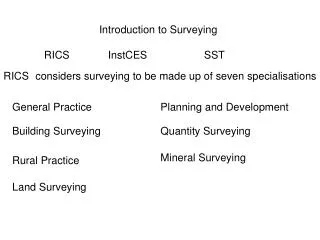
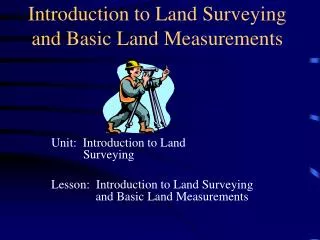
Introduction to Surveying Mr. Vedprakash Maralapalle, Asst. Professor Department: B.E. Civil Engineering Subject: Surveying- I Semester: III. Primary Divisions of Surveying.

E N D
Introduction to Surveying Mr. Vedprakash Maralapalle, Asst. Professor Department: B.E. Civil Engineering Subject: Surveying- I Semester: III eCourseware@AIKTC
Primary Divisions of Surveying We know that the shape of the earth is spheroidal. Thus the surface is obviously curved. Surveying is primarily divided into two types considering the curvature of the earth’s surface. • Plane Surveying • Geodetic Surveying
Plain Surveying • The plain surveying is that type of surveying in which earth surface is considered as a plane and the curvature of the earth is ignored. • In such surveying a line joining any two stations is considered to be straight. • The triangle formed by any three points is considered as a plane triangle, and the angles of the triangle are considered as plain angles. • Surveying is carried out for a small area of less than 250 km2 . • It is carried out by local or state agencies like R & B department, Irrigation department, Railway department.
Geodetic Surveying • The geodetic Surveying is that type of surveying in which the curvature of the earth is taken into account. • It is generally extended over larger areas. The line joining any two stations is considered as curved line. • The triangle formed by any three points is considered to be spherical and the angles of the triangle are considered to be spherical angles. • Geodetic surveying is conducted by the survey of India Department and is carried out for a larger area exceeding 250 km2
Fundamental Principles of Surveying Two basic principles of surveying are: • Always work from whole to the part. • To locate a new station by at least two measurements ( Linear or angular) from fixed reference points.
Always work from whole to the part: • According to the first principle, the whole survey area is first enclosed by main stations (i.e.. Control stations) and main survey lines. • The area is then divided into a number of divisions by forming well conditioned triangles. • The main survey lines are measured very accurately with precise survey instruments. • The remaining sides of the triangle are measured. • The purpose of this method of working is to control accumulation of errors. • During measurement, if there is any error, then it will not affect the whole work, but if the reverse process is followed then the minor error in measurement will be magnified.
To locate a new station by at least two measurements • According to the second principle the points are located by linear or angular measurement or by both in surveying. • If two control points are established first, then a new station can be located by linear measurement. • Let A & B are control points, a new point C can be established.
Instruments Used in Chaining • The following instruments are used while chaining. • Chains • Tapes • Arrows • Ranging rods and offset rods • Pegs • Plumb bob
Instruments Used in Chaining Chains • Metric Chain • Gunter’s Chain or Surveyor’s Chain • Engineer’s Chain • Revenue Chain • Steel Band or band chain
CHAIN • The chain is composed of 100 or 150 pieces of links, made up of 4 mm diameter galvanized mild steel wire. • The ends of the chain provided with brass handles for dragging the chain on the ground. • The end links include the handles. Tallies are provided at regular interval
METRIC CHAIN • The chains are made in length of 20 and 30 meters. • The length of the chain is marked over the handle to indicate the length. • The length of each link is 0.2 m (20cm) in 20m chain is provided with 100 links and 30 m chain divided into 150 links. • Tallies are fixed at every five-meter length and small brass rings are provided at every meter length. • This chain is suitable for measuring distances along fairly level ground.
ENGINEER’S CHAIN • The engineer’s chain is 100ft long and is divided into 100 links. So each link is 1ft. • It is used on all engineering survey works. • The distances measured with the engineer’s chain are recorded in feet and decimals (Tallies are provided at every 10 links i.e. 10 ft).
GUNTER'S CHAIN • It is 66ft long and divided into 100 links. • So each link is of 0.66ft. • It is also called surveyor’s chain. It is very convenient for measuring distances in miles.
REVENUE CHAIN • The revenue chain is 33ft long and divided into 16 links . • It is mainly used in cadastral survey.
STEEL BAND • It consists of a ribbon of steel 16 mm wide with a brass swivel handle at each end and is 20 or 30 m in length. • It is graduated in metres, decimeters, centimeters on one side and 0.2 m links on the other. • For more accurate work, the steel band is preferred.
The advantages of the chain are : • It is very suitable for rough usage. • It can be easily repaired in the field. • It can be read easily and quickly. • It can withstand wear and tear.
Disadvantages of the chain are : • They are heavy and take too much time to open or fold. • They become longer or shorter due to continuous use. • When measurement is taken in suspension, the chain sags excessively.
TAPES The following are the various types of tapes i) Cloth tape or Linen tape ii) Metallic tape iii) Steel tape iv) Invar tape v) Digital tape
Cloth tape or Linen tape • Such a tape is made up of closely woven linen and is varnished to resist moisture. • It is 12 to 16 mm wide and available lengths of 10 & 15m. • It is very light and handy, but not so accurate. For very precise measurements, it is not used. • The linen tape may be used for taking subsidiary measurements such as offsets. • It is easily affected by damp. When the tape gets wet, it shrinks and care should be taken that it is not wound up until is cleaned and dried. • It stretches easily and is likely to twist and tangle. It is therefore little used in surveying.
METALLIC TAPE • It is made from good quality cotton or linen and is reinforced with fine brass or copper wires to make it durable. • This prevents stretching of fibres and is therefore, better than simple linen tapes. • They are also not suited for very precise measurements. • This tape is available in lengths of 15, 20 and 30 m.
STEEL TAPE • The steel tape is made of steel ribbon or stainless steel, of width varying from 6 to16 mm. • The commonly available lengths are 10,15,20,30 and 50m. • It is used for very precise measurements and for checking the accuracy of chain lengths.
INVAR TAPE • Invar tape is made up of an alloy of steel 64% and nickel 36% and possesses a very low coefficient of thermal expansion (0.6 × 10⁻⁴ for 1°C). • It is made in form of a ribbon of width 6mm and is available in lengths of 30, 50 & 100m. • The tapes are extremely brittle and expensive. It is generally used in the triangulation survey conducted by the Survey of India department.
DIGITAL TAPE • This type of device usually has LCD screen connected to a traditional measuring tape. • LCD screen will display the length. • To store & recall measurements. • Useful during home repair or other projects that require frequent & numerous measurements.
RANGING ROD OR OFFSET ROD • Ranging rods are used to range some intermediate points in the survey line. • Such roads are made of seasoned timber or seasoned bamboo, sometimes GI pipes of 25mm. • The length of the ranging rod is either 2m or 3m. The lower end of the rod is pointed and provided with an iron shoe. • Ranging rods are divided into equal parts 0.2m long and they are painted alternately black or red and white.
PEGS • Wooden pegs are used to mark the positions of stations. • They are made of hard timber and are tapered at one end. • They are usually, 2.5 cm square and 15 cm long.
ARROW • They are also called marking or chaining pins, and are used to mark the end of each chain during the process of chaining i.e. used for counting the number of chains while measuring a chain line. • They are made of good quality metallic wires of 4 mm in diameter and are made 400 mm in length, are pointed at one end for inserting into the ground.
PLUMB BOB A plumb-bob or a plummet is a weight, usually with a pointed tip on the bottom, that is suspended from a string and used as a vertical reference line, or plumb-line.
RANGING • The process of establishing intermediate points on a straight line between two end points is known as ranging. • Ranging must be done before a survey line is chained. Ranging may be done direct observation by the naked eye. • Generally, ranging is done by the naked eye with the help of three ranging rods.
Direct Ranging • If the first and last points are intervisible this method is possible. • Stations A and B in which an intermediate point C is to be located. • Point C is selected at a distance slightly less than a chain length. At points A and B ranging rods are fixed. • The assistant holds another ranging rod near C. • Surveyor positions himself approximately 2 m behind station A and looking along line AB directs the assistant to move at right angles to the line AB till he aligns the ranging rod along AB. • Then surveyor instructs the assistant to mark that point and stretch the chain along AC.
Indirect or Reciprocal Ranging • Due to intervening ground, if the ranging rod at B is not visible from station A, reciprocal ranging may be resorted. Figure shows this scheme of ranging. • It needs two assistants one at point M and another at point N, where from those points both station A and station B are visible. • It needs one surveyor at A and another at B. To start with M and N are approximately selected, say M1 and N1. • Then surveyor near end A ranges person near M to position M2 such that AM2N1 are in a line. • Then surveyor at B directs person at N, to move to N2 such that BN2M2 are in a line. • The process is repeated till AMNB are in a line.
UNFOLDING & FOLDING A CHAIN Unfolding: • To open a chain, the strap is unfastened and the two brass handles are held in the left hand and the bunch is thrown forward with the right hand. • Then one chainman stands at the starting station by holding one handle and the other moves forward by holding the other handle until the chain is completely extended.
Folding: • To fold the chain, a chainman should move forward by pulling the chain at the middle. • Then the two halves of the chain will come side by side. After this, commencing from the central position of the chain, two pairs of links are taken at a time with the right hand and placed on the left hand alternately in both direction. • Finally, the two brass handles will appear at the top. The bunch should be then fastened by the strap.