Download
1 / 34
340 likes | 503 Vues
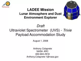
LADEE Mission Lunar Atmosphere and Dust Environment Explorer Draft Ultraviolet Spectrometer (UVS) - Trixie Payload Accommodation Study August 1, 2008. Anthony Colaprete NASA ARC 650-604-2918 Anthony.Colaprete-1@nasa.gov. Instrument Accommodation Review (IAR).

E N D
LADEE MissionLunar Atmosphere and Dust Environment ExplorerDraft Ultraviolet Spectrometer (UVS) - Trixie Payload Accommodation Study August 1, 2008 Anthony Colaprete NASA ARC 650-604-2918 Anthony.Colaprete-1@nasa.gov
Instrument Accommodation Review (IAR) 1. Instrument Description 2. Driving Instrument Interfaces • Electrical Power Interface • Electromagnetic Interference/Compatibility • EMC Design Approach • Command and Data interfaces • Software Interfaces • Mechanical Interfaces (mass & CG) • Thermal Interfaces 3. Instrument FOV Requirements 4. Driving Environmental Interfaces (inc. radiation, contamination, EMI) 5. Driving Operational Requirements • OPS Concept (including instrument modes, etc) • Operational Constraints 6. Programmatic Requirements • Schedule (including payload I&T and System I&T support) 7. Potential Trade Studies:
1. Instrument Description (1 of 5) • The UVS consists of • UV-VIS Spectrometer • 250-800 nm, ~1 nm FWHM optical resolution • 1” f/4 optical design fed by 0.11 NA optical fiber • Hamamatsu S7031-166 1044x64 back-thinned cooled detector • Foreoptics (telescope) • 3” diameter, 1º field-of-view Cassegranian telescope • Optimized for 250-800 nm wavelength range • FC optical fiber connector • Diffusing solar viewer • Transmissive Spectralon diffusing surface protected by sapphire windows • Currently designed with a 140º field-of-view which will be narrowed for LADEE based on operational constraints • Bifurcated optical fiber • Y-shaped fiber will common leg feeding the spectrometer • Top legs feed the foreoptics and solar viewer • Common-leg fibers arranged vertically at the slit of the spectrometer • All hardware has passed proto-qual and TV testing for LCROSS
1. Instrument Description (2 of 5) Foreoptics Alice LCROSS VSP Solar Diffuser
1. Instrument Description (3 of 5) • Trixie Layout for Dual Channel Observations • Two observation modes are proposed: Limb and occultation • These two measurements made with the same instrument using a “Y” split fiber optic cable: UV-Vis Spec FOV~1 deg Fiber Optic Limb Telescope • Signal Strength at Limb Telescope side is ~100x less than that at the solar diffuser assuming the limb telescope where looking nadir (it is possible that the Limb Telescope would be looking to space). • Therefore, while in occultation, very little to no flux would be entering the Limb telescope. • Likewise in Limb viewing mode, only starlight should be entering the occultation diffuser. Occultation Diffuser FOV~1 deg Diffuser contains horizontal polarizer, diffusor (e.g., spectralon), and cover glass (e.g., sapphire)
1. Instrument Description (4 of 5) Alice Test History
2. Driving Instrument Interfaces • Electrical Power Interface • Electromagnetic Interference/Compatibility • EMC Design Approach • Command and Data interfaces • Software Interfaces • Mechanical Interfaces (mass & CG) • Thermal Interfaces
2a) Electrical Power Interface Power Profile as a Function of Instrument Mode
2a) Electrical Power Interface • RS-422 wiring of the UV Spectrometer to the Power Source and Data Interface (LaserCom) MIL-C-24308, Dsub, 15 pin Connector (female)
Electromagnetic Interference/Compatibility • Electromagnetic compatibility (EMC) means that payload instruments are compatible with (i.e., no interference caused by) their electromagnetic (EM) environment, and they do not emit levels of EM energy that can cause EMI (electromagnetic interference) with other devices on the S-S/C
EMC Design Approach • Decouple power • Filter power • Chassis construction • Avoid openings/slots • Gaskets for connectors, seams, etc. Input Power Filtering Aluminum Chassis Without Unshielded Openings Twisted Pairs UV Spectr EMI FILTER Single-PointGround (SPG) • Twisted pair • Shielding • Single Point Grounding • Conduct EMI/EMC testing as assembly Chassis Ground Single Point Grounding Grounded Shields Bonded to Connectors Bonded to Chasses
2b) Command & Data Interfaces • Spectrometer interfaces to SC electronics through a full-duplex RS-422 interface operating at 115,200 bps. Faster data rates are not supported by existing microcontroller. • Spectrometer operations in a command-and-response mode, transferring data only when requested by the SC • Commands are formed by a command header, a command action, an optional command parameter and a checksum • Returned (spectral) data follows the same format of header, data and checksum (2110 bytes total) • Spectra data consists of 1044 unsigned 16-bit intensity values (1024 meaningful pixel values)
2c) Software Interfaces • Supported commands • TEC On/Off • TEC set point • Set Exposure Bracket Mode ## • Set integration time (16-bit version) • Set read main board temperature with acquisition • Initialize the spectrometer • Get current TEC temperature • Perform spectral acquisition • Set Trigger Mode • Write FPGA register • Get time stamp value • Set ASCII mode for data values • Set binary mode (default) for data values • Set the output level shifter divisor ** • Set time stamp divisor ** • Set exposure bracket mode multiplier ## • Sets checksum mode • Read Spectrometer Status • Read board temperature • Get firmware version • Query parameter value (works with any of the above commands that require a parameter) ** controls frequency of heartbeat status signal ## control behavior of exposure bracket mode
2e) Thermal Interfaces • Electronics of the spectrometer dissipate approximately 2.5W. • All electronics are sunk to the bottom of the electronics enclosure. • Detector TEC can dissipate 14.5W when operating. • The bottom surface of the spectrometer is the only surface that needs to be considered as a heat source. 17.5W generated by TEC internal to detector 2.5W sunk to top and bottom surfaces of electronics enclosure Heat path from detector
3) Instrument FOV Requirements 1° 3.6 km Telescope Point as low as possible with 1° FOV: 3.6 km above lunar surface. Diffuser Sun Tracking To view sun requires at least 0.54° FOV. SC pointing error ~ 1° 0.54° No Sun Tracking To see 100 km from lunar surface requires a 13.4° FOV 100 km 13.4 ° Time from sun rise to 100km above surface = 252.3 seconds.
Dust Brightness: Limb View Forward Scatter (5° off sun line), r=100 nm Visual Limit Back Scatter (5° off sun line), r=100 nm Visual Limit
Dust Sensitivity: Limb View Forward Scatter (5° off sun line) SNR for r=100 nm, OD=10-5 Case
4. Driving Environmental Interfaces • When cooler is on (almost always) will need to dissipate ~17 W of heat out of base of spectrometer • Some baffling of telescope will be necessary • Maintain clear FOV to avoid scatter/glint • Solar exclusion zone of +/- 2 degrees from telescope FOV • Bakeout heaters on telescope optics and spectrometer to raise components to approximately 40 C for >48 hours
5. Driving Operational Requirements • See FOV requirements • During limb observations: • Maintain telescope FOV 5 km above lunar surface • Scan continuously with a measurement rate of ~1 scan per 10 sec • During solar occultation measurements: • View sun for more than 250 sec • Scan continuously with a measurement rate of ~1 scan per 1 sec (gives ~0.3 km resolution) • Solar exclusion zone for limb telescope of +/- 2 deg from edge of telescope FOV
6a. Programmatic Requirements • Have ETU delivered to ARC by January 2009 • Want to begin early proto-qual testing • ETU as electrical simulator and mass model? • Need I/O interface defined prior to October, 2008
6b. Unresolved Issues Issues: • Thermal control? Who? What? To provide our own environment will require additional design and add cost. • Integration: multiple separate components? A single plate/box assembly may be required to meet Project payload “autonomy” requirement, but would simplify SC I&T. • Who carries harness (optical and electrical) fastener mass? Who provides these? • Who deploys the contamination door?
7. Potential Trade Studies • Two spectrometers • For an additional $40,000, two spectrometers can be provided by Aurora Design & Technology. This would allow one spectrometer to be dedicated to each of the two measurements. A high degree of fault tolerance is gained (removal of three single-points of failure – spectrometer, optical fiber and power/data cable), as well as the ability to tune the spectrometers’ performance to each of the two measurements. • Increase of aperture of the foreoptics. In limb-viewing mode, the instrument will be starved for photons. Increasing the aperture greatly increases the sensitivity of the instrument:
7. Potential Trade Studies • Addition of single-board computer to spectrometer • Allows for the collection and storage of a significantly larger set of data (current spectrometer microcontroller does not have the computation bandwidth or memory to store data) • Allows for the flight-testing of USB communication between the SBC and the spectrometer (the spectrometer has an unused USB bus). • The only way to reprogram the spectrometer on orbit is through the USB port. • Can be included and still maintain the same command and control as ALICE. • Existing RS-422 communication directly to the spectrometer can co-exist with a secondary communication bus connected to the SBC. If the SBC or the USB bus fails, the flight system can still communicate over the proven RS-422 bus. • Allows for high-speed streaming of data to the Lasercomm system. Highest bandwidth the spectrometer can support while acquiring data is 125 spectra/second * 2110 bytes/spectra ~= 268kb/sec. However, the SBC can buffer a large number of spectra and transfer them at a high bit rate to the Lasercomm system. • If two spectrometers are used, a single SBC could communicate with both spectrometers, or each spectrometer could have its own SBC.
7. Potential Trade Studies • Foreoptics baffles • Current foreoptic design has minimal baffling for stray light. The inside of the enclosing tube is bead blasted. • Increasing baffling will allow for viewing closer to the lunar limb • Penalty is increased length, diameter and/or weight (although weight impact should be minimal)