Download
1 / 18
180 likes | 324 Vues
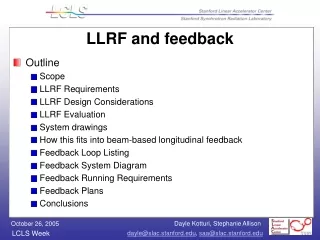
LLRF and Beam-based Longitudinal Feedback Readiness. Outline Overview of the system December 2006 readiness requirements Dependencies Activities to get there – past/present/future Conclusion. Overview of the system.

E N D
LLRF and Beam-based Longitudinal Feedback Readiness • Outline • Overview of the system • December 2006 readiness requirements • Dependencies • Activities to get there – past/present/future • Conclusion
Overview of the system • The low level RF controls system consists of RF phase and amplitude controls at these locations: • Laser • Gun (Klystron 20-6) • L0-A, a.k.a. L0-1 (Klystron 20-7) • L0-B, a.k.a. L0-2 (Klystron 20-8) • L0 Transverse cavity (Klystron 20-5) • L1-S (Klystron 21-1) • L1-X (Klystron 21-2) • L2 - (Klystrons 24-1,24-2,24-3) to control avg phase/ampl of L2 • L3 Transverse cavity (Klystron 24-8) • L3 - 2 sectors of klystrons, S29+S30 • The feedback system consists of a VME chassis connected to LLRF IOCs via private ethernet
Dec 2006 readiness requirements • RF phase and amplitude controls at these locations: • Laser • Gun (Klystron 20-6) • L0-A, a.k.a. L0-1 (Klystron 20-7) • L0-B, a.k.a. L0-2 (Klystron 20-8) • L0 Transverse cavity (Klystron 20-5) • L1-S (Klystron 21-1) • Longitudinal beam-based feedback controls as far as BC1
Dependencies • Use of current downtime to proceed with installation at LINAC Sector 0 • RF hut readiness with racks, AC power, cables and water by July2006 (downtime)
Activities to get therepast/present/future • Five categories of hardware • Low level RF chassis (in-house) • Monitor chassis (in-house with COTS timing) • Fast control chassis (in-house with COTS timing) • Slow control chassis (in-house) • Feedback control chassis (COTS products)
Low level RF chassis (in-house) • What for? Low level RF distribution where EPICS is not required • Where? LINAC Sector 0, the RF hut and klystron stations • Status now: 119, 476, 2856, 2830.5 MHz – 16 way distributions complete • Steps to complete: • by Oct2005: PEP-II master phase shifter • by Nov2005: IQPAU • by Nov2005: 476 MHz master amplifier • by Jan2006: LO chassis
476 MHz master amplifier PEP-II master phase shifter
LLRF Phase Reference System 2830.5 to 2856MHz Divide by 16 Chassis
LLRF Phase Reference System 119 to 476MHz Divide by 16 Chassis
Monitor chassis (in-house with COTS timing) • What for? Local RF phase/amplitude monitoring • Where? Laser, gun, L0-A, L0-B, L1-S • Status now: Evaluating ADCs • Steps to complete: • by Dec2005: evaluation of ADCs (1chan) • by Mar2006: board prototype (4 chan, thermo) • by May2006: final board • by Sep2006: chassis (15 dual channel) • by Oct2006: injector install
Fast control chassis (in-house with COTS timing) • What for? Local RF phase/amplitude control • Where? Laser, gun, L0-A, L0-B, L1-S • Status now: board design • Steps to complete: • by Jan2006: board prototype • by Mar2006: final board • by Sep2006: chassis (6 single channel) • by end of 2006 downtime: injector install
Slow control chassis (in-house) • What for? Phase and amplitude control of the reference • Where? Sector 20 RF hut • Status now: not started • Steps to complete: • by Feb2006: start design • by Mar2006: board prototype • by May2006: final board • by Sep2006: chassis (6 single channel) • by Nov2006: injector install
RF crate • What for? Local feedback control and timing for RF systems • Where? Sector 20 RF hut • Status now: testing EVR • Steps to complete: • evaluate number of signals and processor load to determine number of crates • design and write software • test with simulation and later hardware • during 2006 downtime: install
Feedback control crate (COTS products) • What for? beam-based longitudinal feedback • Where? At sector 20, in RF hut • Status now: software design • Steps to complete: • purchase network switch module if IOC has insufficient ports • by Dec2006: software • by Dec2006: installation
Conclusion • The low level RF system and the global feedback system will be ready for commissioning by December 2006, based on the plan presented.