1 / 54

Geometry Measurement

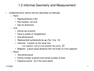
Geometry Measurement. Gauge. Cluster Camera Sensor. Cluster Camera Sensor. Cluster Camera Sensor. Light Sectioning. Laser/Camera Rail Sensor. Light Sectioning. Image Processor. Calibration Target. Calibration Image. Geometry Measurement from Profiles. Curvature. Superelevation.

gay
Télécharger la présentation

Geometry Measurement

An Image/Link below is provided (as is) to download presentation Download Policy: Content on the Website is provided to you AS IS for your information and personal use and may not be sold / licensed / shared on other websites without getting consent from its author. Content is provided to you AS IS for your information and personal use only. Download presentation by click this link. While downloading, if for some reason you are not able to download a presentation, the publisher may have deleted the file from their server. During download, if you can't get a presentation, the file might be deleted by the publisher.

E N D

Presentation Transcript


  1. Geometry Measurement

  2. Gauge

  3. Cluster Camera Sensor

  4. Cluster Camera Sensor

  5. Cluster Camera Sensor

  6. Light Sectioning

  7. Laser/Camera Rail Sensor

  8. Light Sectioning

  9. Image Processor

  10. Calibration Target

  11. Calibration Image

  12. Geometry Measurement from Profiles

  13. Curvature

  14. Superelevation

  15. Simple Superelevation

  16. Not So Simple Superelevation

  17. Fully Compensated Superelevation

  18. Twist

  19. Chord Based Top

  20. Chord Based Top Problems • Car body is the cord – body flex • Distorts track signature • Requires six rail sensor • Cannot see certain faults

  21. Periodic Faults

  22. Space Curve Top

  23. Top - TrackLine

  24. Top – LR3K & UGMS

  25. Top Filtering – Why?

  26. Top Filtering • Filtering limits response of long track features • Solves the problem of signal noise

  27. Top Filtering • Low speed track – short filters (10 – 30m) • High speed track – long filters (50 – 120m) • Butterworth, Bessel ? • Linear phase response, sharper cutoff • Your mileage may vary

  28. Simple Alignment

  29. Partially Compensated Alignment

  30. Fully Compensated Alignment

  31. Inertial Package

  32. Inertial Package Electronics

  33. Inertial System Block Diagram

  34. Laserail VME Chassis

  35. LR3K Data Flow Diagram

  36. Inside of Laserail Beam

  37. CP 63 GRMSGeometry Car Consist

  38. Box Car

  39. Unloaded Gauge

  40. Tube Laser

  41. CP 63 GRMSGeometry Car

  42. Laserail Beam

  43. CP 64Observation Area

  44. CP 64Operators Station

  45. CP 63Geometry Car Interior

  46. Inertial Package Mounting Detail

  47. Geometry Strip Chart

  48. Equipment RequirementsReliability • Reliability • High Reliability to achieve frequency of test • No moving parts • Withstands extreme shock • Custom designed lasers / MTBF of 10,000 hours • Hardened CCD cameras • Complete recording season without corrective maintenance

  49. Laserail Camera on bogie

  50. Locomotive Installation

More Related