Information Modeling Requirement Analysis
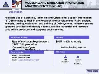
Information Modeling Requirement Analysis. PREPARED BY SARA IZADPANAHI GULSAH TASEL PHILLIPS AGBOOLA. Outline. Introduction The concept of information modeling Information Modeling Procedure Modeling Methodologies Entity Relationship Approach Functional Modeling Approach


Information Modeling Requirement Analysis
E N D
Presentation Transcript
Information Modeling Requirement Analysis PREPARED BY SARA IZADPANAHI GULSAH TASEL PHILLIPS AGBOOLA
Outline • Introduction • The concept of information modeling • Information Modeling Procedure • Modeling Methodologies • Entity Relationship Approach • Functional Modeling Approach • Object Oriented Approach • The holonic philosophy • Case study with UML • Benefits of virtual reality
Introduction The combination of emerging technologies, global competition, and market diversification is imposing a great need for transferring information timely and reliably. Today's manufacturing industry greatly relies on computer technology to support activities throughout a product’s life cycle. Effective and efficient information sharing and exchange among computer systems have been critical issues. For example, in the manufacturing industry, not only can design and manufacturing work be conducted through integrated CAD/CAM processes with electronic linkages to carriers, such as FedEx and UPS, but the entire project and process management activities can be monitored electronically from ideation to product delivery.
Information Modeling • An information model is essential to provide the structure for information that is transferred in a communication. An information model is a formal description of a portion of interest of the real world and that provides explicit rules to enable the data items that populate the model to be interpreted without ambiguity. • An example of an information model is the structure of a sentence in a natural language. The grammar of the natural language provides the rules for interpretation of the information model (sentence) and the data items in the structure are the words of the language. To complete the capability to interpret the communication correctly a dictionary that defines the meanings of the data items (words) is also needed. To achieve unambiguous communication, everyone in the communication process must use the same information model and the same dictionary. If the communication process is between two computer software systems then the information model and the dictionary also have to be computer processable. A dictionary also has to have an information model to provide a structure for the items and their definitions.
Requirement Analysis In the requirements analysis phase of information modeling development, Wand and Weber state[1], “High-quality conceptual modeling work is important because it facilitates early detection and correction of system development errors.” The Standish Group Project, an international consultancy, released a case study report [2] based on more than 30,000 organizations. It stated that for all the software projects developed, only 16% of them succeed. For the rest of 84%, 31% were totally failed, and 53% had cost and time overruns and missing features. According to another report by McConnell [3], the causes of software failure mainly concentrate on: objectives not fully specified (51%) and bad planning and poor estimating (48%). If we can understand customer’s requirements more accurately in the requirements analysis and model the business context to facilitate the implementation of software, then we can increase the probability of success greatly.
Information Modeling Procedure A quality information model should be complete, sharable, stable, extensible, well-structured, precise, and unambiguous. In general, the contents of an information model include - Scope - Information requirements
Scope Information modeling starts with the definition of the scope of the model‘s applicability. The scope specifies the domain of discourse and the processes that are to be supported by the information model. It is a bounded collection of processes, information, and constraints that satisfy some industry need. The scope statements include the purpose as well as viewpoints of the model mentioned bellow: type of product, type of data requirements, supporting manufacturing scenario, supporting manufacturing activities, supporting stage in the product life cycle.
Scope (Cont) The scope definition may be supported by an activity model and/or a data planning model. An activity model is a representation of the application context, data flows, and the processes of the application. It is a mechanism for gathering high level information requirements. A data planning model provides a high level description of the data requirements for the information model, as well as the relationships among the basic data components. It is used as a roadmap to establish interfaces across a wide range of data. A well-defined scope should be accurate, unambiguous, viable, and meet the industrial need. During the course of the modeling, the scope should be revisited and may be refined. Since the scope provides the boundaries of the application domain, it also serves as a guideline for evaluating the “completeness” of the information model.
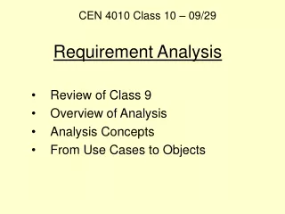
Information Requirement After the scope is defined, the next phase is to conduct a requirements analysis. There is no standard method for collecting information requirements. However, requirements analysis may be accomplished by: - Literature surveys, - Standards surveys, -Domain experts’ interviews, - Industrial data reviews, -State-of-the-art assessments.
Information Requirement (Cont) Depending on the scope, the analysis may include today‘s manufacturing practices, traditional practices, and near future needs. It is important to capture data requirements accurately for the application scope while performing the requirements analysis. Industry reviews of the result of the analysis will help to ensure the completeness and correctness of the information requirements. As the result of the requirements analysis, information requirements should be documented. The definition of each identified information item should be included in the document. This document will be a straw man for developing the information model.
Modeling Methodologies Information modeling is a technique for specifying the data requirements that are needed within the application domain. There are different practices in developing an information model: - Entity Relationship Approach (ER) - Functional Modeling Approach - Object Oriented Approach (O-O)
Entity Relationship Approach (ER) The ER approach focuses on how the concepts of entities and relationships might be applied to describe information requirements. The ER approach is based on a graphical notation technique. The basic constructs in an ER model are the entity type, the relationship type, and the attribute type. The notation is easy to understand and the technique has been useful in modeling real problems. There are commercial tools available to map ER models into commercial DBMSs (Database Management Systems). ER approach is a better selection if data requirements are at the higher levels of detail. • E/R Models are often represented as E/R diagrams (ERDs) that • Give a conceptual view of the database • Can identify some problems in a design The disadvantage of the ER model is its lack of preciseness in supporting the detailed levels.
Entity Relationship Approach (ER) Entity-relationship models use information objects (entities) to represent objects in the real world, specify the properties of real world objects as attributes of the information objects and show the relationships between the objects. Entity-relationship models provide specifications for information about objects by the following capabilities: ….. is_a …… (entity) … has_a ……. (attribute) ….is_related_to…. (one-to-one or one-to-many) My name is Sara
Entity Relationship Approach (ER) • Example: In a University database we might have entities for Students, Modules and Lecturers. Students might have attributes such as their ID, Name, and Course, and could have relationships with Modules and Lecturers (tutor). • E/R Modeling is used for conceptual design • Entities - objects or items of interest • Attributes – facts about, or properties of, an entity • Relationships – links between entities • Relationships are links between two entities • The name is given in a diamond box • The ends of the link show cardinality
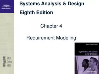
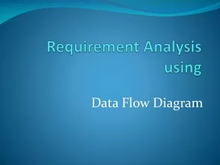
Functional Modeling Approach • The emphasis of the functional modeling approach is placed on specifying and decomposing system functionality. • The functional approach addresses the system's processes and the flow of information from one process to another. It uses objects and functions over objects as the basis. The approach often uses data-flow diagrams. A data-flow diagram shows the transformation of data as it flows through a system. The diagram consists of processes, data flows, actors, and data stores. In the case where functions are more important and more complex than data, the functional approach is recommended. This approach has been in wide use. • Functional Flow Block Diagram • End product of functional decomposition – shows sequence of system activities • Incrementally refine and mark inputs / outputs / controls • Used to illustrate system organization and major interfaces • Build at the later stage of Concept Generation • Sample system functional breakdown - see next page
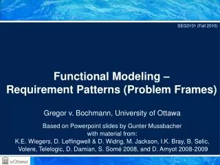
Functional Modeling Level-0 System Requirements Top-level functions Level-1 Function A Function B Function C Function D Function E Function F Second-level functions Level-2 E.2 E.4 E.5 E.1 E.3 E.3 E.6 Figure: System functional breakdown
Levels in Functional Decomposition • Level 0 • This is where you start – the highest level involving one block only, i.e. a block corresponding to your system • Define inputs, outputs and system functionality (requirements) • Level 1 • Typically referred as main system architecture • Architecture means the organization and interconnection between modules. Describe the operation – how modules work together. • Define functional requirements for each module. • Level 2 • Typically shows the organization of components within a single module
Functional Modeling Level-0 Area of a cube Top-level functions Level-1 6 * Area of square Second-level functions Level-2 Length of square * Length of square Example of a System functional breakdown
Object Oriented Approach (O-O) The O-O approach focuses on identifying objects from the application domain first and then operations and functions. In the objected-oriented approach, the fundamental construct is the object, which incorporates both data structures and functions. The building blocks in the O-O model are object classes, attributes, operations, and associations (relationships.) The objected-oriented approach has the following advantages: easier modeling of complex objects, better extensibility, and easier integration with O-O DBMS and O-O programming code. The major obstacle for using the OO approach is that the approach requires a critical paradigm shift in thinking compared with other data modeling approaches
Object Oriented Definitions • Object: An entity that has state, behavior, and identity. • State: Attribute types and values. • Behavior: How an object acts and reacts. • Behavior is expressed through operations that can be performed on it. • Behavior is sometimes referred to as a method or service. • Identity: Every object has a unique identity. • Class: Set of objects that share a common structure and a common behavior.
Object-Oriented Paradigm • Our Word is a collection of collaborating entities President Sales dept. Factory Factory workers Engineers Scientists
Object-Oriented Paradigm • Organize software according to the structure of the world Management Information Object Factory Management Object Sales Dept. Object Worker Object Laboratory Object Design Object
Requirement analysis, Specification, Design Problem P⇒P' Platform M⇒M' Real World W⇒W' Design D⇒D' Programming, Test Program S⇒S‘
Description of the World • How do we describe the world? • Class concept + Relations among classes • Class as a set of “similar objects” in the world • Abstraction :{professor Hashemipour, professor Hacisevki,…} class “professor” • Instantiation : “professor” professor Hashemipour • Class concepts provides economy and reuse of thought and description.
Objects and Classes Cyprus object: abstraction Turkey Iran Italy instantiation class: Country Prof.Hashemipour Prof. Hacisevki hasName: Majid Hashemipour hasphoneNo: 1354 teach hasName: Hasan Hacisevki hasphoneNo: 1386 teach lives-in Class:Professor Hasname:String hasphoneNo:int teach Relationship Attribute Behavior
Relationships Among Classes • Class Hierarchy, Inheritance, • Specialization/Generalization • City< Country < World • Composition, Aggregation, • Automobile=Body+Wheels+Steering+Engine • Association, a general relation between classes People―(lives-in)―Country
Two Major Issues in Object-Oriented Methodology • Object-Oriented Analysis/Design • BOOCH, OMT, UML, Catalysis methods • Constraints, Formal Approach, Analysis Patterns,Unified Process, … • Object-Oriented Programming • OO languages: Smalltalk, C++, Java • Design Patterns, Frameworks , Class Libraries …
Object Oriented vs. Entity Relationship • Most of concepts for entity-relationship modeling will correspond to concepts • in object-oriented modeling • - Object-oriented model has MORE features Object Oriented ER Entity type Class Entity instance Object Relationship Association Inheritance of attributes Inheritance of attributes Inheritance of behavior No representation of behavior Inheritance : methods and/or attributes defined in an object class can be inherited or reused by another object class. association : relationship between different objects of one more classes.
Choice of Modeling Methodology hascolour Rolls, be thrown AREA OF A RHOMBOID? BALL? Choosing an appropriate modeling methodology is a judgment that must be made at the beginning of the modeling work. In general, an information model, developed in any methodology, is a representation of entities, attributes, and relationships among entities. However, each information model has a different emphasis. The emphasis often depends on the viewpoint associated with the model. Occasionally there are multiple viewpoints for the model. The viewpoints of the model help to decide the type of information modeling methodology to be used.
Choice of Modeling Methodology -Differences between functional and objected oriented programming can be summed up as follows: -In object oriented programming everything (or almost everything) is treated as an object that can be modified and that can perform tasks, or in OOP speak one might say objects have state and behavior. What it buys you (among other more advanced things) is: modularity, and data hiding. -Here is an example: You might have an object that models a ball, from above the ball can be modified (i.e. you can change its state) for example you may be able to change the color of the ball. It can also perform tasks (i.e. it also has behavior) for example the ball can roll, or be thrown. As an object it is bundled neatly in a package that provides methods to change the state of the ball, and to make the ball perform actions. This package is usually called a module, in addition to the methods used to change state, and perform actions, the module also has data that is used to store any state information needed.
Choice of Modeling Methodology Because this module is a complete package that models your object completely, the module can easily be reused in many different applications. Once it is written and working anyone should be able to use the module without fully understanding internals. For example all one needs to know is that they want a red ball to throw. Here is a good resource on OOP: "Object-Oriented programming concepts” [1] In functional programming what you have basically are a set of functions each of which performs a task. Selectively executing these function results in the solution to the problem at hand. For example you might have a function that takes the coordinates. of a square computes the area, and you may have another function that computes the area of a triangle. By executing the square function 6 times you could compute the area of a cube. Or by executing a combination of the square and triangle functions you could compute the area of a rhomboid. As you can see you can build quite complex systems based on simple functions.
Modeling Language Quite a few information modeling languages, for different methodologies, have been developed. These information modeling languages provide various ways of formally representing an information model. An information modeling language is a formal syntax that allows users to capture data semantics and constraints. Languages for information models have continued to evolve: the Integrated Computer Aided Manufacturing (ICAM) Definition Language 1 Extended (IDEF1X) ,the EXPRESS Language, and the Unified Modeling Language (UML) are some examples. In general, the languages are presented in two forms: - Graphical form - Textual form The graphical form is designed primarily for humans, while the textual form is for both humans and machines.
Unified Modeling Language (UML) UML is a modeling language for specifying, visualizing, constructing, and documenting the artifacts of software systems. It was conceived originally by Grady Booch, James Rumbaugh, and Ivar Jacobson. It is a graphical representation and its based on the objected-oriented paradigm. UML contains notations and rules and is designed to represent data requirements in terms of O-O diagrams. UML organizes a model in a number of views that present different aspects of a system. The contents of a view are described in diagrams that are graphs with model elements. A diagram contains model elements that represent common O-O concepts such as classes, objects, messages, and relationships among these concepts.
BACKGROUND • Arthur Koestler : “The Ghost in the machine” (1967) • Herbert Simon (1969): Complex systems will evolve from simple system more rapidly if there are stable intermediate forms than if there are not • Two watchmakers (Bios and Mekhos) • “Wholes” and “part” in an absolute sense do not exist The Holonic idea is a new paradigm develop to organize activities and meet the agile, scalable ,robust and fault-tolerant requirements, overcomes many difficulties faced by existing convectional, rigid systems in manufacturing, offices etc
The Holonic concept Holonic idea or concept is not a method or a process but a philosophy. A guiding philosophy for effective and efficient way of getting a performance better than the traditional approaches in use today This concept can be applied to our day to day life, activities as long as efficiency is needed to be measure. Holonic idea have been applied in offices, business, industry, university. So, it becomes paramount for us to have a full understanding of this guiding philosophy for efficiency Next slide explains the Holonic philosophy and shows how it works.
What are Holons? It is a combination of holos (a greek word meaning whole) and suffix on (meaning particles or part) A holon, as Koestler devised the term, is an identifiable part of a system that has a unique identity, yet is made up of sub-ordinate parts and in turn is part of a larger whole. It is an autonomous and co-operative building block of a manufacturing system for transforming, transporting, storing and/or validating information and physical objects.
Holon’s Properties • Autonomy: the capability of an entity to create and control the execution of its own plans and/or strategies • Co-operation: a process whereby a set of entities develops mutually acceptable plans and executes these plans. • A holon self-regulates and respond to the environmental changes by using flexible strategies, and the changes are fed back to the center of its controller to continuously adjusts its course of action. The essential attributes of holons includes autonomy and cooperativeness
FOUR QUADRANTS OF HOLONS • Four quadrants of holons is developed by a scientist called Ken Wilber as a part of his Integral theory • Wilber observes that each holon (and every holarchy) has at least four fundamental, different, irreducible dimensions of existence. These can be seen as four types of 'truth', actively pursued by different disciplines. • Wilber's proposition is that each of the four quadrants of each holon must develop in balance with each other .If one quadrant develops at a faster rate than the others, the holon will exhibit unhealthy distortions retarding the holon's functionality with the other holons at its level and above. Eventually, the holarchy will collapse back to a level of balance before it can undertake further sustained development.
Holonic Systems Holarchy: a system of holons that can co-operate to achieve a goal or objective. The holarchy defines the basic rules for co-operation of the holons and thereby limits their autonomy. Holonic manufacturing system: a holarchy that integrates the entire range of manufacturing activities from order booking through design, production, and marketing to realize the agile manufacturing enterprise.
HOLONIC SYSTEMS Cooperative relationships among holons
HOLONIC SYSTEMS The stability of holons and holarchies stems from holons being self-reliant units, which have a degree of independence and handle circumstances and problems on their particular level of existence without asking higher level holons for assistance. Holons can also receive instruction from and, to a certain extent, be controlled by higher level holons. The self-reliant characteristic ensures that holons are stable, able to survive disturbances. The subordination to higher level holons ensures the effective operation of the larger whole.
HOLONIC SYSTEMS In manufacturing, the term ‘Holonic’ is used to stress the concept of highly decentralized coordination and control in production system. This is especially true in the tasks of (ontology) knowledge representation, communication architecture, negotiation, coordination and cooperation principle and algorithms as well as in the corresponding standardization. In contrast to traditional approach, a Holonic manufacturing system is constructed in a bottom-up fashion by integrating Holons in such a way that they collaborate to provide an array of system-wide characteristic .These behavioral attribute include flexibility, robustness, self-similarity, openness and so forth. The appearance and the whole existence of Holon's are tightly connected with the requirement of system reconfigurability to support the manufacturing agility, and holons are consider as the lowest level of granularity in the reconfuguration tasks.
Comparison with other approaches(1) • Existing approaches • Hierarchical control • Top-down • Strictly defined modules and their functionality • Autonomy of, and communication b/w modules limited • Sensitive to perturbation • Rigid architecture • Expensive to develop • Difficult to maintain • Low agility and responsiveness
Comparison with other approaches(2) • Existing approaches • Heterarchical control • No hierarchy • Power to the basic modules (“agents”) • Can react adequately to changes in the environment & in the manufacturing system itself • Very agile • Simple to design, understand and maintain • Predictability low • Need for abundant resources and homogeneous environment
Comparison with other approaches(2) • Holonic vs. hierarchical and heterarchical control • Autonomy to the individual modules (holons) • Loose hierarchy (holarchy) • Differences from the traditional hierarchical control • Holons: • Can belong to multiple hierarchies • Can form temporary hierarchies • Do not rely on the proper operation of each holon in the hierarchy