Download
1 / 14
140 likes | 170 Vues
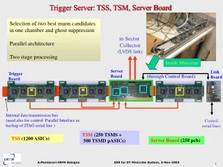
Trigger Server: TSS, TSM, Server Board. Selection of two best muon candidates in one chamber and ghost suppression Parallel architecture Two stage processing. to Sector Collector (LVDS link). Inside Minicrate. Server Board. Link Board. Trigger Board. (through Control Board).

E N D
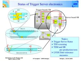
Trigger Server: TSS, TSM, Server Board Selection of two best muon candidates in one chamber and ghost suppression Parallel architecture Two stage processing to Sector Collector (LVDS link) Inside Minicrate Server Board Link Board Trigger Board (through Control Board) Internal data transmission bus (used also for control: Parallel Interface as backup of JTAG serial line ) Control serial lines TSM (250 TSMS + 500 TSMD pASICs) TSS (1200 ASICs) Server Board(250 pcb) A.Montanari-INFN Bologna
TSS: chip layout and technology 4.5 mm Alcatel, CMOS 0.5 mm, 3.3 V 20000 gates 208 pins Power consumption: ~300 mW Selection of 2 best candidates from 4 TRACOs Ghost suppression Fully configurable Control access through JTAG and Parallel Interface Spying through snap registers Stand alone internal test features Documentation: CMS IN 2002/011 A.Montanari-INFN Bologna
TSS: design and test philosophy TSS working rules and specs VHDL design HW test SW test Event Generator Pattern Unit VHDL simulator Gate-level sim. post-layout sim. C++ Device Emulator Device Patter Unit Output Analyzer A.Montanari-INFN Bologna
TSS: test system VME pattern generator and readout up to 100 MHz (Pattern Unit) Device under test SW controls all test options: Provides monitoring and configuring Generates, transmits and receives patterns (billions of random patterns!!) Checks output with emulation A.Montanari-INFN Bologna
TSS: production and screening ~2700 packaged chips not testeddelivered in 2002 Tested in house ~1300 chips with a yield of 92 % (we need1140 + 15% spares) Test bonding through JTAG Test sorting: in different configurations up to 50 MHz +/- 10% Vcc (100k patterns/configuration) Test access through Parallel Interface Test Snap/Test registers ….all chip functionalities 2 min/chip A.Montanari-INFN Bologna
TSS: radiation tolerance Irradiation at: Cyclotron Research Center (CRC), Universite Catholic de Louvain (UCL), Louvain-la-Neuve, Belgium with 59 MeVprotons TID effects: stable up to 30krad (10LHC years: 0.02 krad) SEU (six observed): MTBF > 3.3 LHC years (90% c.l.) Flux: 3x10⁸ protons/(cm2.s) Total dose: 380 krad over 6 chips 256 FFs monitored at 150kHz A.Montanari-INFN Bologna
TSM: architecture (redundancy) theta TB data TSMD LVDS selected TRACO data from 3 phi TBs controls to/from 6 TBs TSMS to Sector Collector TSS data from 6 phi TBs select bus TSMD LVDS selected TRACO data from 3 phi TBs theta TB data control bus to/from CB Selection of 2 best candidates from up to 6 TSS Ghost suppression Data trasmission to Sector Collector Bottleneck for both trigger and data path Backup mode: if TSMS fails, TSMDs perform sorting on quality bits (full efficiency for single muon and dimuon pairs at Track Finder level) if one TSMD fails, only half chamber is lost A.Montanari-INFN Bologna
TSM: system design isol isol isol TMS TCK JADD(3:0) BADD(3:0) nPWRenD0 nPWRenD1 nPWRenSort nPWRenSort nPWRenD0 nPWRenD1 isol isol isol isol isol TSMD 0 TSMD 1 TSMS TDO isol TDI nPWRenD0 isol isol isol isol nPWRenD0 nPWRenD1 nPWRenSort TSMS and 2 TSMD are 3 distinct ICs: independent power lines in case of chip failure each I/O line can be disconnected two independent ways for monitoring and configuring: 1. Local JTAG 2. Parallel access bus with ad hoc protocol (Parallel Interface) Example of redundancy: local JTAG chain A.Montanari-INFN Bologna
TSM: radiation tolerance TSM technology: Actel programmable ASICs (model A54SX32-3; package PQ208) Irradiation at: Cycloctron Research Center (CRC), Universite Catholic de Louvain (UCL), Louvain-la-Neuve, Belgium with protons 59 MeV Total dose: 4 pASICs irradiated up to 40 krads/chip (1 of them up to 70 krads) (total fluence 1.4x10¹² protons/cm2) 450 bits monitored/chip: only 1 SEU !! MTBF > 4.6 LHC years (90% c.l) A.Montanari-INFN Bologna
Server Board: layout Top side: Server Board 16 layers PCB Absorbed current: ~600 mA on 3.3 V ~600 mA on 5.0 V Control access through JTAG and Parallel Interface 20.6 cm 9.5 cm Bottom side: part of Control Board TSMS TSMD A.Montanari-INFN Bologna
Server Board: test setup Pattern Units (pattern generator and readout module) Crate VME Vme board with CPU Pentium II 80 bits @ 40 MHz Rs232 PC serial port Server Board Trigger Link Rx 232 bits @ 40 MHz 232 bits @ 40 MHz LVDS link – data serialized @ 480 MHz 2 copper cables FTP class 6– 40 m Adapter Board A.Montanari-INFN Bologna
Server Board: test results TSM and SB work as expected up to 44 MHz of clock frequency and transmitting output through cables long up to 40 m (test of Trigger Link, see F.Odorici talk) Server Board Adapter Board Trigger Link Rx A.Montanari-INFN Bologna
Server Board: production TSM: TSM functionality tested with “surgical” and random pattern (109) 3x250 pASIC Actel 0.35 micron delivered and fused after design validation SB: Pre-production of 5 delivered in March 03: successfully tested and design validated 1 SB installed in the minicrate and tested in May 03 test beam: valid integration test (see R.Travaglini talk) Pre-series production of 35 SB delivered last September: to be used for 2003 minicrate production and tuning of burn-in procedures Tender for full production finished: 50 boards will be delivered spring 2004 200 boards in autumn 2004 all boards will be tested with our test system in house A.Montanari-INFN Bologna
Burn-in procedures TSS: done on Trigger Board (F.DalCorso talk) Server Board: all components are commercial MIL-STD883 (method 1015, 5004) procedures suggests 60 degrees for 15 days: eliminate infant mortality without affecting the lifetime of the components test in bunches of 40 boards, powered and clocked evaluate and calibrate the procedure on first bunch A.Montanari-INFN Bologna