Variable Speed Indoor Blower Motor Operation Guide - Technical Conference 2002
390 likes | 460 Vues
Learn how to set up and operate ECM™ variable speed motors for optimal indoor airflow. Discover the wiring options, modes, and reminders for efficient motor operation in heating and cooling systems.

Variable Speed Indoor Blower Motor Operation Guide - Technical Conference 2002
E N D
Presentation Transcript
Technical Conference - Panama City Beach, Fl - 2002 Variable Speed Indoor Blower Motor Robert Helt
Normal Blower Operation • Set Switches 1 & 2 for System Tonnage • Set 3 & 4 for 350,400, or 450 CFM/Ton • Set 5 & 6 for Time Delay / Enhanced Mode • Set 7 & 8 for Desired Heating Airflow • Verify CFM with Flashing LED • Cont. Fan Airflow is 1/2 Cooling CFM • Cycle Power For New Switch Settings
Variable Speed Motor Operation • G - On / Off Command for the Motor • Y - Selects Cooling Or Heat Pump Heating CFM • Ylo - Selects Low Speed Cool or HP Heating CFM • O - Tells Motor Cooling Mode is Selected • BK - Selects De-Humidify Mode when O is ON, or PWM Input for Variable Speed Mode Operation • W1 - Selects Low Heat CFM, Elect. or Gas • W2 - Selects High Heat on Gas Furnaces • W3 - Selects High Heat on Electric Heat (If Used)
Time Delay Operation • The Time Delay Mode Senses Y or Ylo and G • The Off Time Begins When Y or Ylo & G Turn Off, simultaneously. • The Off Time Airflow will be 100% or 50% of the Last Airflow Depending on Option Selected • If Continuous Fan Mode is Selected, No Delay Operation Will Occur Because: G On, Cont Fan, is Considered a New Mode • Comfort “R” Mode, Delay Off CFM, will be 50% of the Last Requested CFM
Variable Speed Motor Continuous Fan Wiring Options • Normal 50% of Cooling Airflow • Optional 40%, 80% and 100 % of Cooling Airflow Can be Provided • Some Wiring Tricks are Required • Get Your Thinking Cap On
G G BK R BK to R Jumper Circulation AirflowFan Power(3 ton typical) 50%(normal) 60 - 100 watts Note: Only wiring involved is shown. Normal or Comfort “R” Mode. Single Speed or Two Speed systems.
G to Y Jumper BK to R Jumper G Y BK R G Y Y Circulation Airflow Fan Power(3 ton typical) 100 %400 - 500 watts Note: Only wiring involved is shown. Single Speed System. Normal Mode Only.
G Y O G Ylo O Y BK Y O Jumper G to Ylo to O Jumper Y to BK Circulation AirflowFan Power(3 ton typical) 40% (normal) 60 - 100 watts Note: Only wiring involved is shown. Single Speed system. Normal Mode.
G Ylo O G Ylo O BK Ylo O Jumper G to Ylo to O Circulation AirflowFan Power(3 ton typical) 40% (normal) 60 - 100 watts Note: Only wiring involved is shown. Two Speed system. Normal Mode.
G Y O G Y O BK Y O JumperG to Y to O Circulation Airflow Fan Power(3 ton typical) 80%200 - 350Watts Note: Only wiring involved is shown. Single Speed System. NON - Comfort “R” Mode.
Cooling Mode andHumidistat Operation • Motor in Cooling Mode, when O Energized • BK is Humidistat Enable, 24Vac • Airflow is Reduced by 20% when BK is OffandO is On (Motor is in Cooling Mode) • De-Humidify mode - O is On, BK is Off • Delay Off airflow will be Reduced by 20% in De-Humidify mode
G Y G Y BK R Y Humidistat BK to R Jumper Replaced by Humidistat Humidistat opens on Rising Humidity Note: Only wiring involved is shown. Normal Mode Only, Not Comfort “R”. Do not use Humidistat with Comfort “R”.
De-Humidify Mode • Operates in Cooling Mode, O - On • G, Y or Ylo, O, and BK to Operate • Install Humidstat BK to R to De-Humidify • Provides 80% Airflow When Humidistat isOpen, BK is Off • Delay Off airflow will be Reduced 20% if Humidistat is Open
Comfort “R” Mode“Enhanced Mode” • Comfort “R” Mode (Enhanced Mode) Operates in Cooling or Heat Pump Heating Modes, Air Handlers. Cooling Mode only in Gas Furnace, with “O”. • G, Y or Ylo, are the Only Inputs Required, A/H. In a Gas Furnace Application, O is also Required. • Comfort “R” Mode Operates in Low Speed and High Speed for Two Speed Systems
10% MOISTURE REMOVAL
1 Stage, Comfort “R” Mode “Enhanced Mode” SYSTEM AIRFLOW (CFM) 100% 80% Only if required FIRST STAGE 50% Dehumidify Warm Air Enhanced Comfort Enhanced Efficiency OFF OFF 3 1 7.5 minute minutes minutes COMPRESSOR OPERATION ON OFF
Variable Speed Reminders • If Enhanced Mode (Comfort “R”) is Selected, Jumper R to BK • If Enhanced Mode is Selected, Set 400 CFM/Ton • On Air Handlers, Comfort “R” Mode works in Heating and Cooling • On Gas Furnaces, Comfort “R” Mode works in Cooling when “O” is energized • On Packaged Units, G is not the Master on-off switch
VSPD Reminders, cont. R to BK Jumper, Reminders • Remove BKJumper if Humidistat is installed • Remove if Variable Speed Mode, PWM Input • Remove for Special Continuous Fan Modes • Leave in for Standard Operation • Leave in for Enhanced Mode Operation
G Y O G Y BK R O Y O BK to R Jumper Circulation AirflowFan Power(3 ton typical) 50% (normal)60 - 100 watts Comfort “R” Can Operate in Heat Pump and Cooling Modes
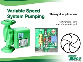
Variable Speed Tools Two Colors Test Wire Go - No Go Cable Trouble Shooter Kit Order Pub. No. 34-3403-01
Variable Speed Tools The Test Board is used in place of the Variable Speed Fan Motor
Problem DiagnosisUsing Troubleshooting Tools • Verify Signals to Motor w/Troubleshooter • LED’s Indicate Which Dip Switches are in the ON Position • LED’s Indicate Which Control Lines are Energized • Verify Motor Operation w/Go-No Go Cable
Problem DiagnosisUsing In-Board Electronics • Apply “G” and Motor Should Operate • If Motor Runs Very Slow With Fast Flashing CFM LED - No Programming, Replace Module • Wrong CFM Indication or Flashes: Check Dip Switch Settings and 24 Volt Inputs • Check for Label Indicating Proper Part Numbers and Mnemonics
Replace the Module Not the Motor/Module combinationReturn Analysis Confirms less than 10 Total Motor Failures
Variable Speed Draft InducerTroubleshooter BoardPub No. 34-3404-01
Variable Speed Module Programming • PC Card and Cable for Local Parts Distributor Programming • Four Blank Modules for 56 Variable Speed Applications • Reduced Replacement Inventory - Saves Money • Improves Your Responsiveness to the Dealer & Homeowner • Internet Software Updates • Availability - ??? ??? ??? • Limited Quantities
Variable Speed Indoor Motor Programmer • Shipped with PC card, cables and instruction manual • Software to run the program will be downloaded through the Internet • The software will reside on the users PC • When new VS software is released for production the web site will be updated • Before the software is downloaded the user must agree to the LICENSING AGREEMENT GE HAS PROVIDED • FAILURE TO ABIDE BY THE AGREEMENT MAY RESULT IN LEGAL RECOURSE BY GE