IP Routing
IP Routing. Internet Addresses. A unique identifier for an interface within a network 32-bit number Consists of two fields Network id used primarily for routing Host id used to number hosts within a network. IP Addressing. IP address classes: A, B, C, D, E. Classful Addresses. Class A.

IP Routing
E N D
Presentation Transcript
Internet Addresses • A unique identifier for an interface within a network • 32-bit number • Consists of two fields • Network id used primarily for routing • Host id used to number hosts within a network
IP Addressing IP address classes: A, B, C, D, E
Classful Addresses Class A 7 bits 24 bits hostid netid 0 1.0.0.0 to 127.255.255.255 • 126 networks with up to 16 million hosts Class B 14 bits 16 bits hostid 0 netid 1 128.0.0.0 to 191.255.255.255 • 16,382 networks with up to 64,000 hosts Class C 21 bits 8 bits 0 netid hostid 1 1 • 2 million networks with up to 254 hosts 192.0.0.0 to 223.255.255.255
Class D 28 bits 0 1 1 1 multicast address 224.0.0.0 to 239.255.255.255 • Up to 250 million multicast groups at the same time Class E 27 bits 1 1 0 1 1 240.0.0.0 to 254.255.255.255
Reserved Host IDs (all 0s & 1s) • Broadcast addresses: • Broadcast address has hostid set to all 1s • 255.255.255.255 • A.B.C.255 • Special case • Internet address used to refer to network has hostid set to all 0s • 0.0.0.0 and A.B.C.0 can be either treated as a broadcast or discarded
Private IP Addresses • Specific ranges of IP addresses set aside for use in private networks (RFC 1918) • Range 1: 10.0.0.0 to 10.255.255.255 • Range 2: 172.16.0.0 to 172.31.255.255 • Range 3: 192.168.0.0 to 192.168.255.255 • Loopback network • 127.0.0.0 • Typically only 127.0.0.1 is used
Example of IP Addressing 128.140.5.40 128.135.40.1 H Interface Address is 128.135.10.2 Interface Address is 128.140.5.35 H Network 128.135.0.0 Network 128.140.0.0 R H H H 128.135.10.20 128.135.10.21 128.140.5.36 Address with host ID=all 0s refers to the network Address with host ID=all 1s refers to a broadcast packet R = router H = host
Problems with Classes • Did not account for popularity of Internet • Classes do not match reality well • 254 vs 65534 vs 16 million hosts • 254 hosts is too small for most organizations • 16 million hosts is way to large • 128 vs 16384 vs 2 million networks • Fixed by Classless Inter-Domain Routing (CIDR) • Removes classes (hence classless) • Network boundary can be at any bit in address • Forces network mask to be specified
CIDR Addresses • Classless Inter-Domain Routing • Classes A, B, C too rigid • Add flexibility on a bit level instead of byte level • W.X.Y.Z/B • B is the number of bits that constitute the network address • /8 is class A • /16 is class B • /24 is class C
Subnetting • A subnet is a physical segment in a TCP/IP environment that uses IP addresses derived from a single network ID. • By partitioning the bits in the host ID into two parts, Subnet ID and the Host ID, a single Network Address can be used to uniquely define a set of subnets. • The number of hosts available for the Network address will be distributed among the subnets.
Subnet Mask and IP • A subnet mask is a 32-bit address used to block or “mask” a portion of the IP address to distinguish the network ID from the host ID. • Each host on a TCP/IP network requires a subnet mask, either a default subnet mask or a custom subnet mask. • A default subnet mask is used on TCP/IP networks that are not divided into subnets. • In the subnet mask, all bits that correspond to the network ID are set to 1. All bits that correspond to the host ID are set to 0.
Subnetting • Variable length subnet masks • Could subnet a class B into several chunks Network Host Network Subnet Host 1111.. ..1111 00000000 Mask
Subnetting Example • Assume an organization was assigned address 150.100.x.x • Assume < 100 hosts per subnet • How many host bits do we need? • Seven • What is the network mask? • 11111111 11111111 11111111 10000000 • 255.255.255.128
196 200 150 3-bits 5-bits Subnetting Example Divide 196.200.150.0 into 15 sub-networks. Needs to borrow 5-bits from the host part to have 15 sub -networks. Subnet mask: 11111111.11111111.11111111.11111000 ie., 255.255.255.248 or we can write it as 196.200.150.0 / 29
Subnetting Example • Organization has Class B address (16 host ID bits) with network ID: 150.100.0.0 • Create subnets with up to 100 hosts each • 7 bits sufficient for each subnet • 16-7=9 bits for subnet ID • Apply subnet mask to IP addresses to find corresponding subnet • Example: Find subnet for 150.100.12.176 • IP add = 10010110 01100100 00001100 10110000 • Mask = 11111111 11111111 11111111 10000000 • AND = 10010110 01100100 00001100 10000000 • Subnet = 150.100.12.128 • Subnet address used by routers within organization
H1 H2 150.100.12.154 150.100.12.176 150.100.12.128 150.100.12.129 150.100.0.1 R1 To the rest of H3 H4 150.100.12.4 the Internet 150.100.12.55 150.100.12.24 150.100.12.0 150.100.12.1 R2 H5 150.100.15.54 150.100.15.11 150.100.15.0 Subnet Example
Variable Length Subnet Masking (VLSM) Consider a class “C” IP address : 200.10.15.x Default (subnet) mask (SM): 255.255.255.0 SM 255.255.255.192 /26 2 subnets @ 62 hosts SM 255.255.255.224 /27 6 subnets @ 30 hosts SM 255.255.255.240 /28 14 subnets @ 14 hosts SM 255.255.255.248 /29 30 subnets @ 6 hosts SM 255.255.255.252 /30 62 subnets @ 2 hosts When do we need to use different subnet masks?
Variable Length Subnet Masking (VLSM) E1 E2 R R Leased Line Colombo Head Office 50 hosts Kandy Branch Office 25 hosts
Variable Length Subnet Masking (VLSM) E1 E2 R R Subnet 2 Colombo Head Office 50 hosts Kandy Branch Office 25 hosts Subnet 3 Subnet 1
Variable Length Subnet Masking (VLSM) E1 E2 1 1 1 1 R R 50 25 Colombo Head Office 50 hosts Kandy Branch Office 25 hosts No of IP Addresses Required 50+25+1+1+1+1 = 79
Variable Length Subnet Masking (VLSM) For the serial link – needs only 2 IPs SM – 255.255.255.252IPs – 200.10.15.5 /30 and 200.10.15.6 /30 For Kandy subnet – needs 26 IPs SM – 255.255.255.224IPs – 200.10.15.33 /27 E2 and 200.10.15.34 /27 to 200.10.15.58 /27 (m/c) For Colombo subnet – needs 51 IPs SM – 255.255.255.192IPs – 200.10.15.65 /26 E1 and 200.10.15.66 /26 to 200.10.15.115 /26 (m/c)
Variable Length Subnet Masking (VLSM) E1 E2 200.10.15.5/30 200.10.15.6/30 R R 200.10.15.33/27 200.10.15.65/26 Colombo Head Office 50 hosts Kandy Branch Office 25 hosts 200.10.15.66 – 200.10.15.115/26 200.10.15.34 – 200.10.15.58 /27
IP Routing Basics - Background • Every IP datagram contains the destination internet address • The network part of the address uniquely identifies the single physical network that is part of the larger Internet • All hosts and routers that share the same network part of their address are connected to the same physical network and can directly communicate with each other • Routers interconnect the various networks
IP Routing Basics • So, a host (or router) simply needs to determine if a destination is local or not • Compare the network part of the interface’s address and the destination address • If same, local • If not same, remote • If local, send directly to destination • If remote, send to a router on the local network
IP Routing Basics • If it’s that easy, what’s the big deal? • Topology isn’t always as simple as it sounds • If a network has multiple routers, how is the best router for next hop chosen? • How do routers efficiently route the packet to the final destination? • What happens if routers go down? • Manually configuring all hosts and routers with topology information isn’t desirable
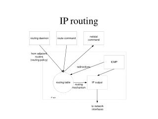
Forwarding Table • Can display forwarding table using “netstat -rn” • Sometimes called “routing table” DestinationGatewayFlags RefUseInterface 127.0.0.1 127.0.0.1 UH 0 26492 lo0 192.168.2. 192.168.2.5 U 2 13 fa0 193.55.114. 193.55.114.6 U 3 58503 le0 192.168.3. 192.168.3.5 U 2 25 qaa0 224.0.0.0 193.55.114.6 U 3 0 le0 default 193.55.114.129 UG 0 143454
Forwarding Table Structure • Fields: destination, gateway, flags, ... • Destination: can be a host address or a network address. If the ‘H’ flag is set, it is the host address. • Gateway: router/next hop IP address. The ‘G’ flag says whether the destination is directly or indirectly connected. • U flag: Is route up ? • G flag: router • H flag: host
Processing the Routing Table • Use routing table to find route • Host route with matching destination • Network route with matching destination network (only network numbers compared) • Otherwise, use default route • Once route found, packet is sent to gateway or local destination depending on gateway flag
Building Routing Tables • Manually entered information • LAN routing protocols • ICMP redirects • ICMP router discovery • Intradomain (interior) routing protocols • RIP (Routing Information Protocol) • OSPF (Open Shortest Path First) • IGRP (Interior Gateway Routing Protocol) • EIGRP (Enhanced IGRP) • Interdomain (exterior) routing protocols • EGP(Exterior Gateway Protocol) • BGP(Border Gateway Protocol)
Manually Building Routing Tables • Typically only add a default route • Can add other entries, but best to use automatic techniques • For Windows or UNIX, use route command
Host B Other Networks Network 2 ICMP Redirect Datagram Hop 3 3 2 Router B Host A Router A Network 1 1 2 Datagram Hop 1 Datagram Hop 2 ICMP Redirects 1 - Host A sends datagram to it’s default router, Router A. 2 - Router A forwards datagram to Router B and sends ICMP Redirect to Host A to tell it to send future datagrams destined for Host B to Router B. Host A creates a host route for Host B’s address to Router B. 3 - Router B forwards datagram to Host B, the final destination.
RIP - Routing Information Protocol • Originally developed as part of BSD UNIX • RIP uses a distance-vector algorithm • Best route is the one with least hops (distance) • Maximum distance supported is 15 hops • Does not factor in link speed and other metrics • RIP takes time to converge • 3 minutes typical • 7 minutes worst case • RIP V2 added network masks for CIDR
RIP - Routing Information Protocol • Protocol is fairly simple • Each router broadcasts an advertisement every 30 seconds or when a received advertisement changes the routing table • Each advertisement includes the cost of reaching each network through that router • <network-address[, mask], distance> pairs • Each router increments the cost as it propagates the reachability information
RIP Example Initial routing table for router A: 10.1.0.0 1 DestinationNext HopInterfaceHops 10.1.0.0 0 1 1 10.2.0.0 0 2 1 10.3.0.0 0 3 1 Router A Routing Table: A 2 3 10.2.0.0 10.3.0.0 After router B’s advertisement received: DestinationHops 10.2.0.0 1 10.4.0.0 1 10.6.0.0 2 Router B only knew of its direct networks and router C’s D B DestinationNext HopInterfaceHops 10.1.0.0 0 1 1 10.2.0.0 0 2 1 10.3.0.0 0 3 1 10.4.0.0 B 2 2 10.6.0.0 B 2 3 Router A Routing Table: 10.4.0.0 10.5.0.0 E C 10.6.0.0 10.7.0.0
RIP Example 10.1.0.0 Final routing table for router A: 1 A DestinationNext HopInterfaceHops 10.1.0.0 0 1 1 10.2.0.0 0 2 1 10.3.0.0 0 3 1 10.4.0.0 B 2 2 10.5.0.0 D 3 2 10.6.0.0 B 2 3 10.7.0.0 D 3 3 2 3 10.2.0.0 10.3.0.0 D B Router A only receives direct advertisements from routers B and D. Router C and E’s routes are learned from router B and D. 10.4.0.0 10.5.0.0 E C 10.6.0.0 10.7.0.0