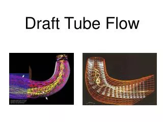
Draft Tube Flow
Draft Tube Flow. u 1. c 1. w 1. u 2. w 2. c 2. Swirl at the outlet from Francis runners. u 2. b 2. c 2. w 2. c 2u. u 2. b 2. c 2. c 2m. w 2. c 2u. u 2. b 2. c 2m. w 2. c 2. Phenomenon in the draft tube flow Swirl flow Flow in bend

Draft Tube Flow
E N D
Presentation Transcript
u1 c1 w1 u2 w2 c2 Swirl at the outlet from Francis runners u2 b2 c2 w2 c2u u2 b2 c2 c2m w2 c2u u2 b2 c2m w2 c2
Phenomenon in the draft tube flow • Swirl flow • Flow in bend • Positive pressure gradient in the diffuser - separation
Swirl flow in draft tubes • Strong coupling between the flow field and the pressure gradients Anisotropic turbulence • The turbulence is influenced by the geometry and the velocity • The draft tube flow is sensitive to the inlet conditions (velocity and pressure) • A vortex filament is present
Mean Axial Velocity Swirl flow
Vortex breakdown Vortex breakdown is present when a negative axial velocity occurs in the center of the flow. Vortex breakdown occurs when S > 1
Rankine Vortex Swirl flow
Swirl flow Vortex filament at part load Vortex filament at full load
Flow in bends A - A A A
Flow in bends Newton’s 2 law From Bernoulli’s equation Free Vortex
Results: The hydraulic design of the draft tube gives secondary flow and therefore a reduced efficiency
The Navier Stokes equations in Cylindrical coordinates r-direction: q-direction: z-direction:
Euler equations r-direction: q-direction: z-direction:
r-direction • Assume steady state solution • Assume axis symmetry • Assume g-force to be neglectible
0,1 m Pressure [Pa]
0,1 m Pressure [Pa] Radius [m]
0,2 m Pressure [Pa]
0,2 m Pressure [Pa] Radius [m]
0,4 m Pressure [Pa]
0,4 m Pressure [Pa] Radius [m]