Download
1 / 22
490 likes | 1.49k Vues
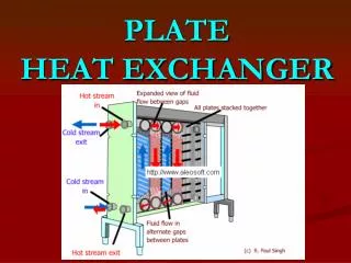
Chapter 4.2 : Flow Across a Tube Bundle Heat Exchanger (Tube Bank). Heat transfer to or from a bank (bundle) of tubes in cross flow is found in many industrial applications, such as steam generator in a boiler or air cooling in the coil of an air conditioner.

E N D
Chapter 4.2: Flow Across a Tube BundleHeat Exchanger (Tube Bank)
Heat transfer to or from a bank (bundle) of tubes in cross flow is found in many industrial applications, such as steam generator in a boiler or air cooling in the coil of an air conditioner. The geometric arrangement is shown in the figure. One fluid moves over the tubes, while a second fluid passes through the tubes. The tube rows of a bank are either staggered or in-line (aligned) in the direction of the fluid velocity (V). The configuration is characterized by 1) The tube diameter (D). 2) The transverse (normal) pitch (ST). 3) The longitudinal (parallel) pitch (SL).
The heat transfer coefficient for a tube in the first row is approximately equal to that for a single tube in cross flow, whereas larger heat transfer coefficients are associated with tubes of the inner rows. The tubes of the first few rows act as turbulence promoters, which increases the heat transfer coefficient for tubes in the following rows. Little change occurs in the convection coefficient for tubes beyond the fifth row. Tube arrangement in a bank. (a) Aligned. (b) Staggered.
Average heat transfer coefficient for the tube bundle: 1)For airflow across tube bundles composed of 10 or more rows, Grimison has obtained a correlation of the form: where, and C1 and mare constants listed in Table (1):
Table (1) : Constants for Grimison’s correlation for flow over a tube bank of 10 or more rows
2) For other fluids flow across tube bundles composed of 10 or more rows, the average Nusselt number becomes All properties appearing in the above equations are evaluated at the film temperature, where 3)For flow across tube bundles composed of number of rows less than 10 (NL < 10), a correction factor C2 may be applied such that
where the correction factor C2 is given in Table (2): Table (2): Correction factor C2for NL < 10 Calculation of the maximum fluid velocity (Vmax) The maximum Reynolds number (Remax) for the foregoing correlations is based on the maximum fluid velocity (Vmax) occurring within the tube bank.
Case of aligned (in-line) arrangement: The maximum velocity occurs at the transverse plane A1.From the continuity equation (mass conservation) V = inlet velocity = incoming flow velocity = free stream velocity Case of staggered arrangement: The maximum velocity may occur at either the transverse plane A1 or the diagonal plane A2.
If A1 < A2: If A2 < A1:
Zukauskas correlation: More recent results have been obtained, and Zukauskas has proposed the following correlation for the heat transfer coefficient for flow across tube bundles:
Where all properties except Prw are evaluated at the bulk temperature [Tb = (Ti + To)/2]. The constants C and min the correlation of Zukauskas given by equation (4) for a tube bank in cross flow are listed in Table (3). If NL < 20 rows, a correction factor C2may be applied such that The correction factor C2 is listed in Table (4)
Table (3): The constants C and min the correlation of Zukauskas
Table (4): Correction factor C2for NL < 20 , Re > 103 Logarithmic Mean Temperature Difference: where Ti and Toare temperatures of the fluid as it enters and leaves the bank, respectively.
Calculation of the outlet temperature (To): The outlet temperature, which is needed to determine Tlm , may be estimated from N = total number of tubes in the bank NT = number of tubes in the transverse plane (normal to the flow) Calculation of the heat transfer rate (Q): The heat transfer rate from the bank of tubes may be computed from
Calculation of the pressure drop (p): The power required to move the fluid across the tube bank is often a major operating expense and is directly proportional to the pressure drop associated with flow across a tube bank, which may be expressed as = correction factor of a square, in-line tube arrangement or an equilateral triangle, staggered tube arrangement. f = friction factor. The friction factor f and the correction factor are plotted in the following figures for in-line (aligned) tube bundle arrangement as well as for staggered tube bundle arrangement.
friction factor f and correction factor for in-line (aligned) tube bundle arrangement
friction factor f and correction factor for staggered tube bundle arrangement
Example: Pressurized water is used for space heating or industrial process applications. In such cases it is customary to use a tube bundle heat exchanger in which the water is passed through the tubes, while air is passed in cross flow over the tubes. Consider a staggered arrangement for which the tube outside diameter is 16.4 mm and the longitudinal and transverse pitches are 34.3 mm and 31.3 mm respectively. There are seven rows of tubes in the airflow direction and eight tubes per row. The tube surface temperature is at 70oC, while the air upstream temperature and velocity are 15oC and 6 m/s, respectively. Determine: a) The air-side average heat transfer coefficient (using Zukauskas correlation). b) The air outlet temperature. c) The rate of heat transfer per unit tube length. d) The air-side pressure drop.
Data: Tube bundle, staggered arrangement, D = 16.4 mm, SL= 34.3 mm, ST = 31.3 mm, NL = 7, NT = 8, Tw = 70oC, T = Ti = 15oC, V = 6 m/s. L = 1 m Required: a) , b) To , c) , d) p. Solution: For air at T = Ti = 15oC, = 14.8210-6 m2/s, Pr = 0.71, k = 0.0253 W/m.K., = 1.217 kg/m3, cp = 1007 J/kg.K. For air at Tw = 70oC, Pr = 0.701. For air at Tf = (Tw + Ti )/2 =(70 + 15)/2 = 42.5oC, Pr = 0.705
Since A1 < A2 , the maximum velocity occurs on the transverse plane, A1 It follows from the tables that
With , and = 1.04 and f = 0.35