Download
1 / 16
170 likes | 438 Vues
Linear Induction Machine Design for Instructional Laboratory Development. Jason Wells. University of Illinois at Champaign - Urbana. Sponsors: Grainger Center for Electric Machinery and Electromechanics Emerson Electric Motor, Inc. Power Affiliates Program May 23, 2002. Introduction.

E N D
Linear Induction Machine Design for Instructional Laboratory Development Jason Wells University of Illinois at Champaign - Urbana Sponsors: Grainger Center for Electric Machinery and Electromechanics Emerson Electric Motor, Inc. Power Affiliates Program May 23, 2002
Introduction • Why Linear Induction Motors? • Growing applications in industry • Similarity to its rotary counterpart • Open Frame Construction • Access to the secondary • Flexibility University of Illinois at Champaign-Urbana
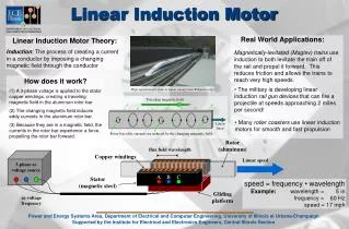
Hardware Design • Linear Induction Primary • Sizing • Magnetizing Inductance of the Stator • Alternate Topologies • Single- or Double-LIM • Various Secondary Designs • Motor Mount System • Primary Mount System • Secondary Mount System University of Illinois at Champaign-Urbana
Linear Induction Primary • Sizing • Limiting physical size for ease of use in the laboratory • Limiting Speed for practicality Vs = 2Tpf (1) • Number of Poles University of Illinois at Champaign-Urbana
Linear Induction Primary (cont.) • Magnetizing Inductance of the Stator • Energy Approach with Finite Element Analysis (2-D) • Solve the scalar elliptic PDE shown below for A, where A is the magnetic vector potential, is the permeability and an input, and J is the current density and also an input, and returns a solution of A: -[(1/)A] = J (2) • Due to the 2-D analysis, A will be of the form A = (0,0,Az) and now the equation below can be solved for the magnetic flux density B: B = (A/y, A/x,0) (3) University of Illinois at Champaign-Urbana
Linear Induction Primary (cont.) Plot of the magnetic flux density B from the FEA University of Illinois at Champaign-Urbana
Linear Induction Primary (cont.) • Energy stored in the stator can be found from B and knowledge of the mesh pattern, where V is the volume: E = (1/2)*B*(B/)*V (4) • Inductance of the geometry is then found using equation (4) where As is the area of the slot carrying current density J. L = 2*E/(J*As)2 (5) University of Illinois at Champaign-Urbana
Linear Induction Primary (cont.) Final dimensions of the linear induction motor stator (stacked 5.1 cm, 36 poles, 3 phase, #18 gauge wire, 60 turns per slot) University of Illinois at Champaign-Urbana
Alternate Topologies • Single-LIM/Secondary (no iron) right • Single-LIM/Secondary (iron) right bottom • Double-LIM/Secondary (no iron) below University of Illinois at Champaign-Urbana
Motor Mount System • Primary Mount System • Dual Rail System • Nylon linear Bearings • Flexibility • Accommodate Single and Dual Sided Primary LIM Configurations • Allow Adjustability of the Air Gap between Primary and Secondary University of Illinois at Champaign-Urbana
Motor Mount System (cont.) • Secondary Mount System • Smooth and Precise Linear Motion • Dual Rail System • Linear Ball Bearing Mounts • Flexibility • Mounting platform • Simple Aluminum Bar (with or without back iron) • Wound Secondary • Permanent Magnet Secondary • Adjustable Traveling Distance University of Illinois at Champaign-Urbana
Motor Mount System (cont.) Prototype mount system shown in a Double-LIM configuration with a bare aluminum sheet as the secondary University of Illinois at Champaign-Urbana
Experimental Verification • During construction the target fill factor for the slots was approximately 30% rather than the expected 50% • Comparison of adjusted calculated and measured parameters of the stator University of Illinois at Champaign-Urbana
Educational Development • Presentation of the LIM and associated laboratory work strengthens student understanding • Motor Construction • Slot Design • Winding strategy • Laminations • Relationship between number of poles, pole pitch, electrical frequency, and mechanical speed • Ability to vary design parameters, such as air gap length and rotor type, that are typically fixed in rotary machinery • Access to rotor components University of Illinois at Champaign-Urbana
Educational Development (cont.) • Potential Laboratory Exercises • Machine Characterization • Observation and Characterization of the Effect of the Air Gap Length on Machine Performance • Observation of Various Motor Topologies • SLIM/DLIM • Wound secondary • Permanent Magnet Secondary University of Illinois at Champaign-Urbana
Summary • A Linear Induction Motor has been presented which offers several advantages for an educational environment • Potential laboratory exercises have been discussed University of Illinois at Champaign-Urbana