
Comprehensive Rocket Design Diagram with Measurements and Component Details
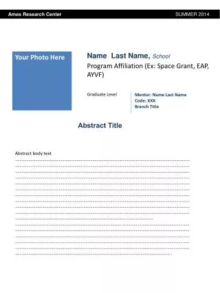
This project report includes a detailed rocket design diagram with comprehensive measurements of the airframe and fins. It identifies all components, including the number of fins and the total weight with payload. The report also outlines the center of pressure (CP) and center of gravity (CG) locations, along with a materials list for the recovery harnesses. Detailed wiring diagrams for altimeters and systematic steps for preparation are provided, including explosive charge specifications and motor selection with thrust-to-weight calculations demonstrating compliance with performance criteria.

Comprehensive Rocket Design Diagram with Measurements and Component Details
E N D
Presentation Transcript
Team Name School Name
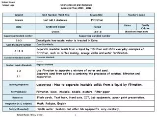
Rocket design diagram with measurements • Include drawing of rocket identifying all components • Include measurements of air frame and fins. • Identify the number of fins. • Total weight of rocket with payload • Location of CP • Location of CG • Materials list
Recovery Harness • Show drawing of recovery harnesses for each part of rocket • Identify harness material and strength • Identify linkages and load limits • Identify eye bolts and mounting methods
Altimeters • Show wiring diagram of altimeters • Document altimeter preparation steps • Specify the quantity of black powder to be used and the volume to be pressurized and calculated pressure level • Specify how sections are secured before ejection charges separate sections • friction fit • shear pins • other • Identify how charges are set off • e-matches • flash bulbs • other
Motor Selection • Identify primary motor selection • Calculate thrust to weight ratio • thrust ratio must be a minimum of 5:1 • Identify back up motor selection • Calculate thrust to weight ratio • thrust ratio must be a minimum of 5:1 • Attach simulation plots for each motor and expect weight


![[Insert School Name]](https://cdn3.slideserve.com/5570965/slide1-dt.jpg)