Advanced Modeling and Simulation of the C-5 Aft Cargo Loading System
This paper explores the comprehensive modeling and real-time simulation of the C-5 Aft Cargo Loading System, focusing on mechanical and hydraulic systems. It discusses the system's background, including the aircraft's aft pressure door, which serves crucial functions for aerial deliveries and drive-in loading. Utilizing CATIA, DADS, and EASY5 models, the development of solutions to address reliability and operational efficiency challenges is outlined. Results include hydraulic modifications increasing opening speed while maintaining performance criteria for aircraft operations, leading to optimized loading procedures.

Advanced Modeling and Simulation of the C-5 Aft Cargo Loading System
E N D
Presentation Transcript
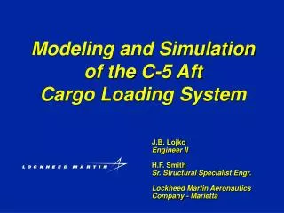
Title Modeling and Simulation of the C-5 Aft Cargo Loading System J.B. Lojko Engineer II H.F. Smith Sr. Structural Specialist Engr. Lockheed Martin Aeronautics Company - Marietta
Agenda • System Description & Background • DADS Model • EASY5 Model • Solution Development • Testing • Solutions, Part 2 • NASTRAN Model • Conclusions & Lessons Learned
Mechanical System Description • Plug-type Door - Seals Aft Cargo Envelope • Height - 11.4 ft • Width - 19.0 ft • Door Weight 1845 lb • Carries Cabin Pressure Loads in Flight & Cargo or Vehicle Loads for Drive-in Loading • Pressure Door Opens Up for Aerial Delivery & Truck-bed or Down for Drive-in Loading • 2 Sets of Hinges and Actuators, Upper and Lower, Left and Right
Mechanical System Description • Aerial Delivery System • Aerial Delivery System (ADS) Requires Installation of a Pilot Parachute on the Lower Half of the Door • Pilot Parachute and Associated Hardware Weight 558 lb • Supporting Fuselage Structure Found to be Very Flexible
Hydraulic System Description • 3000 psi System • Opening • 2 gpm Split to 1 gpm at Actuators • Ramp Blocker Valve • Balanced Relief Valve • Closing • Initial Lift - Fuse • Slow Down - Fuse
First Contract • Fatigue Problems with Upper Hinge Prompted USAF to Place LM Aero-Marietta Under Contract to Improve the Reliability of this System • Initial Contract 1996 - Less Than Four Month Project • Geometry and Kinematics Created in CATIA • Ground Test Performed to Validate Simulations • Analysis Performed in CATIA Using CAT/DADS • Several Solutions Proposed • Hydraulic Modifications - Slow Door Opening • Structural Modifications - Increase Strength in Selected Areas
First Contract Actuator Load Comparison, Normal Operation, Test vs. DADS
First Contract Actuator Load Comparison, Slow Operation, Test vs. DADS
Second Contract • Follow On Contract 1999 • Incorporate Hydraulic Modifications to Reduce Door Opening Speed • First Attempt Failed • Use DADS/Plant & EASY5 to Analyze All Proposed Hydraulic Modifications Prior to Testing • Using Analysis-Led Design the Second Attempt at Modifying the Hydraulics was a Success
Model Definition • Model Simplified - Flexibility Greatly Reduced • 16 Bodies • 6 Control Elements • Left & Right Actuator Distance, DistanceD, Force • Forces • 1 Contact Force - Door Stop • 2 TSDAs - Lower & Upper Fuselage Stops • 2 RSDAs - Flexibility in Torque Arm/Hook
Model Definition • Approximately 20 Joints • Other • Curves - Door Stop Driver
Model Definition • 62 Components • Main Control Valve • Custom - HV Library • Balanced Relief Valve (Simplification) • Pilot-to-Open Check Valve • Fuses - Variable Orifice that Closes After Specified Volume of Flow is Sensed
Model Definition, cont. • Actuators - AP Component for use with DADS Model Extension Component • Ramp Blocker Valve - Critical that Pressure was Measured • Simple Fixed Orifice
Simulations • Conduct Simulations to Determine the Best Combination of Flow Regulators • Performance Criteria - Load Reduction vs. Opening Time • Constraint - Slowing Opening Time Could Impact Aircraft Operation • Current Flight Profile Could Change for ADS Preparation
Flow Regulators • Manifold, Cartridge Valve Flow Regulator • Fluid Regulators • Modify Current 2.0 gpm Flow Regulators • .5 gpm & 1.0 gpm • MS-Type Flow Regulator • Parker Hannifin • 1.5 gpm & 2.0 gpm
Tests • Baseline Test • Verify Door Operates Properly • 1st Test • 1.0/2.0 gpm Flow Regulators • Regulators Delivered as Specified • 2nd Test • .5/1.5 gpm Flow Regulators • Modified 2.0 -> .5 gpm Could Not Perform as Desired
Test Results • Baseline • Operated Properly • Approximately 10 second Opening • 1st Test • Approximately 19 second Opening • Predicted 21.29 second Opening
Test Results, cont. • 2nd Test • Approximately 22 second Opending • Predicted 40 seconds with Constant .5 gpm Flow • 2nd Test - Better Performance • Re-Run Simulations with Variable Flow Rate Regulator
Loads & Pressures • Goal of First Model • Hydraulic Modification Will It Work? • How Long to Open & Close Door • Not Concerned with Loads • After Test, Model Fidelity Improved to Assist Loads & Structural Analysis Organizations • Variable Flow Regulator Simulated • Balanced Relief Valves Added
Model Definition • Structural Flexibility in Fuselage Modeled • DADS/Flex Used to Model Torque Arm/Hook • Forces • 10 Bushings • MSC NASTRAN Model Used to Find Spring Constants • 4 RSDAs - Damping Only - Friction, Any Uncertainties
Model Definition • Flexible Bodies • Left & Right Torque Arm & Hook • MSC NASTRAN • 1st Simulation Craig-Bampton Modes not Defined Properly • Continue Work Upon Return to Marietta
DADS/Flex • Craig-Bampton Mode Errors • Fixed Constraints • Free Constraints • Axis Orientation • Local z-axis Parallel to Global y-axis for Revo & Cyli Joints • Several Axes Rotated about Global y-axis to Achieve Correct Load Path
Torque Fitting Representation • Torque Fitting and Arms Isolated • Interface Points Defined • Shaft Inboard and Outboard Bearings • Actuator Attach • Door/Arm Contact • Inboard Roller • Restraint Hook • Structure Idealized in NASTRAN • Mirrored for Right Side
Fitting Back-Up Representation • Fuselage Plug from FS 1964 to 2178 Used. Detailed Idealization of Back-up Frame Included. • Five Interface Points Chosen • Actuator Point • Inboard Upper Support Point • Outboard Upper Support Point • Inboard Lower Support Point • Outboard Lower Support Point • Mirrored for Right Side
NASTRAN Analysis Run • Normal Modes • Imposed Deflection Force Matrix Generation • Unit deflections imposed on interface point DOF’s one at a time with remaining interface point DOF’s constrained. • Analyses performed for each side separately for each substructure.
HYDRAULICS & CONTROLS MONODETAIL MODELS DYNAMICS MECHANICAL SYSTEM BUILDUP KINEMATICS (CAT/DADS) Methodology MECHANICAL SYSTEM PROTOTYPE
Integrated CAE • CATIA • Work From One Geometry Model (CATIA) • DADS (CAT/DADS) • Define Load Paths • NASTRAN • EASY5 • Clearly Define Requirements for Interfaces • INTEGRATED CAE WILL SAVE TIME & MONEY