Overview of the PS Orbit Trajectory Measurement System (TMS) and its Expert GUI
This document presents an overview of the PS Orbit Trajectory Measurement System (TMS) and its related functionalities, including the acquisition and processing of trajectory data from multiple pickups at CERN. The system supports various measurement types such as Bunch-By-Bunch Trajectory Measurement and Beam Orbit Measurement. An Expert GUI is introduced for diagnostic purposes, allowing users to select cycles for data acquisition and visualize trajectory and bucket status in real-time. This system enhances the efficiency of monitoring and controlling particle trajectories in accelerators.

Overview of the PS Orbit Trajectory Measurement System (TMS) and its Expert GUI
E N D
Presentation Transcript
1/21 Training PS OrbitExpert GUI Stéphane Bart Pedersen BE-BI-SW 2011
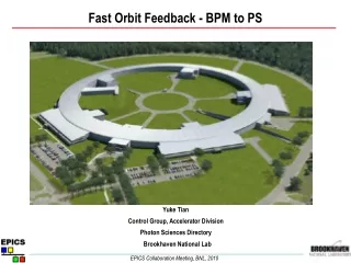
About the PS Orbit Presentation 2/21 Control server for the PS orbit acquisition system Status 2009 [CERN-BE-Note-2009-030 ] • Hardware specialist : Jeroen Belleman (BE-BI-PI). • 80 pickups (H and V). • TMS : Acquisition system at 125Mhz (hardware + software) connected to the pickups. 3 seconds of continuous acquisition using a rolling buffer. • BPMOPS : FESA server running on dcpspuct and connected to TMS. PPM single acquisition + gain control + calibration. • Performances : Max 200000 points can be retrieved per cycle (ex: 8 bunches/80 pickups/300 turns trajectories).
About the PS Orbit Trajectory Measurement System (TMS) 3/21 • The TMS uses configuration tables to control the acceleration cycle sequences, machine filling patterns and fine timings for each possible beam type. The position measurement requires that several signals be aligned with the bunch. The tables contain many parameters that can be adjusted by the hardware expert (not OP). Some parameters, notably the filling patterns, can be adjusted by the operators from the application program level via FESA.
About the PS Orbit Real-time overview 4/21 • The TMS system uses a fixed list of hardware timing events along the cycle. At the same time, the FESA server triggers three different RT actions consecutively. Before each cycle, the BPMOPS informs the TMS about the desired trajectories (Prepare). At the end of the flat top, it imports data from the TMS and it processes the data (Publish). On user request, it can also trigger an acquisition of the diagnostic signals (sigma, gate, baseline restore and local oscillator) with a resolution of 8ns during a time window of 32us (Acquire).
About the PS Orbit Position calculation and gain settings 5/21 • Raw sigma and delta data (turn by turn and 1ms averages) are provided by the TMS and converted into positions using the formula shown below (1). The FESA server calculates the MRPs by making an average of the orbit positions over all pickups. • Gains
About the PS Orbit Type of measurements 6/21 • Bunch-By-Bunch Trajectory Measurement : Trajectory measurements of all bunches for all pickups over a specified number of turns (up to 200 000 measurements in total) starting from a specified delay in number of revolution periods. Position [bunches][number of turns][H |V] • Beam Orbit Measurement : The mean position of all bunches and for all pickups over a millisecond at 1ms interval. Position [number in ms][40H | 40V] • Beam Mean Radial Position (MRP) : The mean of the beam orbit measurement over all pickups at 1ms interval. Position [number in ms][H |V]
Expert GUI - Overview About it 7/21 • This is only an Expert GUI! • This application can help OP to make diagnostics but it is not designed to replace any OP application. It will not be modified and adapt to any OP requests. • OP application needed if this one will miss functionalities.
Expert GUI - Overview First opening 8/21
Expert GUI – Overview After an acquisition 9/21
Expert GUI – Acquisition How to proceed 10/21 • Selection of a cycle • The left part of the panel is all the PS cycles and in the right part it is the running cycles. You have to click on the left part to select a cycle. • Identification of the cycle in the super cycle • If the same cycle occurs more than once in the super cycle and if you select a value in the box, you will get the data during the cycle selected that has an id (red value) > the box value. • Get data! • Status : Has it succeeded? • The status bar is in green color if the acquisition • went ok and you will see the bucket status panel updated.
Expert GUI – Acquisition Type of acquisition panels - Trajectory 11/21 • Trajectory and trajectory YASP panels • All • Display of the n turns trajectories • including H and V plans, bucket • status panel, bunch/turn/pickup • selection panels, PU positions vs. • Turns and Turn position vs. PU. • The bucket status panel shows • how each buckets are filled using • raw sigma signal. If it is in black color then it is empty, gray means not used otherwise a color is shown in either relative scale (the maximum sigma value will be red) or absolute scale (the red color is the maximum signal that the PU can return).
Expert GUI – Acquisition Type of acquisition panels – Trajectory (2) 12/21 • Trajectory and trajectory YASP panels • Bunch • Display of the bucket status. Same panel as the smaller one. • Polar • Polar plot panel that display H and V positions (same turn) • on a X and Y axis. It is possible to select different PU for H and V. • Anim • Overview plot that shows all the polar plots per PU along the PS ring. • MRP • MRP calculated with trajectories for a given list of selected PUs. • Info • Information data to describe the acquisition (time stamp, • number of turns…).
Expert GUI - Acquisition Bucket status panel 13/21
Expert GUI – Acquisition Type of acquisition panels - Orbit 14/21 • Orbit • All • Display of the n ms orbits including H and V plans, time/pickup selection panels, PU positions vs. ms and ms position vs. PU. • Polar • Polar plot panel that display H • and V positions (same time) on • a X and Y axis. It is possible to • select different PU for H and V. • Info • Information data to describe the • acquisition (time stamp, number • of ms…).
Expert GUI – Acquisition Type of acquisition panels - MRP 15/21 • MRP • All • Display of the n ms MRP including H and V plans. • Polar • Polar plot panel that display • H and V positions (same time) • on a X and Y axis. • Info • Information data to describe • the acquisition (time stamp, • number of ms…).
Expert GUI – Settings Prepare BPMOPS for an acquisition 16/21 • Selection of the gain • The FESA server prepares the PU amplifiers before the start of a cycle. 16 gain values are defined but only gains from 1E9 to 5E12 are operational. • Start time (CTIM) • The TMS acquires, on demand, trajectories from a given CTIM in the cycle. • Fine value in turns (relative to the start time) • It is possible to adjust the start time in turns number.
Expert GUI – Diagnostic & Expert Settings • Overview 17/21
Expert GUI – Diagnostic Make a diagnostic (1) 18/21 • Visualization of the low level hardware signals. A 2D plot window shows 4 plot curves of sigma, BLR, gate and LO. Panel with settings for the acquisition of these curves (ex: start time, pickup).
Expert GUI – Diagnostic Make a diagnostic (2) 19/21 • Before requesting a new diagnostic acquisition via the “Refresh Data” buttons, it is possible to select the pickup, the time delay in us relative to the timing trigger also select from this panel (ex: INJECTION). • The refresh data will ask once the server to acquire the diagnostic and all the diagnostic plots will be refreshed.
Expert GUI – Diagnostic TMS expert settings 20/21 • TMS configuration panel that allows the user to modify, for a selected cycle, the state and period table files. Different periods (state periods) are present in the cycle period. Gate, BLR, LO, harmonic number, filling pattern can be changed. Whenever the user selects a period, the application updates a plot panel (left side) with the hardware settings used. On the right side, the user can modify these settings and change the filling pattern as well. • It is possible to copy settings from one cycle to another. This initial settings refers to the reference files containing the last valid setting parameters saved by the HW expert. This functionality should be rarely used and each copy should be report in the logbook.
Expert GUI – Diagnostic No acquisition? 21/21 • Red status • BPMOPS server is down • TMS system down or not acquiring • Problem with timing not received • Only black buckets • No beam! ;) • Gate not properly aligned • Gain too high • Expert setting file for this cycle not ok • Application very slow too use • Not my fault, it is JAVA! ;) • Sometime your console is slow • because too many processes are running • FESA CMW problem Restart it! (+ report in logbook) Contact me or Jeroen Make a diagnostic Contact me or Jeroen Buy a Mac! Contact me