Download
1 / 42
420 likes | 452 Vues
Explore the architecture, requirements, and challenges of the fast orbit feedback system at NSLS-II for stable operation. Topics covered include FOFB data measurement, delivery, and system design considerations.

E N D
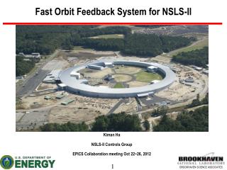
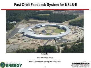
Fast Orbit Feedback - BPM to PS Yuke Tian Control Group, Accelerator Division Photon Sciences Directory Brookhaven National Lab EPICS Collaboration Meeting, BNL, 2010
Outline • NSLS-II orbit feedback system requirements • Fast orbit feedback system architecture • Overall architecture • BPM FOFB data measurement • BPM FOFB data delivery – fiber SDI link • FOFB calculation – compensation for each eigenmode • Corrector setpoints to power supply system • Progress • Summary EPICS Collaboration Meeting, BNL, 2010
NSLS-II orbit feedback system requirement NSLS-II technical Requirements & Specifications EPICS Collaboration Meeting, BNL, 2010
NSLS-II orbit feedback system requirement Long ID Short ID Dispersion Region Lattice function for one cell EPICS Collaboration Meeting, BNL, 2010
NSLS-II orbit feedback system requirement NSLS-II orbit stability requirement , hence must hold orbit stable to In short insertion, Orbit stability requirements can be met using orbit feedback. EPICS Collaboration Meeting, BNL, 2010
NSLS-II orbit feedback system requirement Noises source need to be suppressed • Long term - Years/Months • Ground movement • Season changes • Medium - Days/Hours • Sun and Moon • Day-night variations (thermal) • Rivers, rain, water table, wind • Synchrotron radiation • Refills and start-up • Sensor motion • Drift of electronics • Local machinery • Filling patterns • Short - Minutes/Seconds • Ground vibrations • Traffic, Earth quakes • Power supplies • Injectors • Insertion devices • Air conditioning • Refrigerators/compressors • Water cooling • Beam instabilities in general EPICS Collaboration Meeting, BNL, 2010
NSLS-II orbit feedback system requirement Typical noises source frequency in light source EPICS Collaboration Meeting, BNL, 2010
NSLS-II orbit feedback system requirement Beam motion from long term group motion Lihua Yu EPICS Collaboration Meeting, BNL, 2010
Orbit feedback system architecture • Overall architecture: slow and fast correctors EPICS Collaboration Meeting, BNL, 2010
Orbit feedback system architecture Fast orbit feedback system in one cell EPICS Collaboration Meeting, BNL, 2010
Orbit feedback system architecture NSLS-II two tier device controller architecture Cell 1 Cell 30 Cell 2 Cell 29 Cell 3 Storage Ring SDI link SDI link Cell 17 Cell 15 Cell 16 EPICS Collaboration Meeting, BNL, 2010
Orbit feedback system architecture NSLS-II FOFB latency/bandwidth ● BPM group delay: less than 50 us (estimate) ● BPM data from 8 BPMs transferred to cell controller: 3.5us ● BPM data distribute among the storage ring 6us (12us if one link broken) ● FOFB calculation with separate mode compensation: 3.5us ● Set power supply by PS SDI link: 5.4 us (11us if one link broken) ● Fast corrector PS bandwidth (10 degree phase shift): 8KHz ● Corrector magnet/chamber bandwidth: 1KHz (measured with Inconelbeampipe, 10 degree phase shift) EPICS Collaboration Meeting, BNL, 2010
Orbit feedback system architecture BPM FOFB data measurement Joseph Mead EPICS Collaboration Meeting, BNL, 2010
Orbit feedback system architecture BPM FOFB data measurement Kiman Ha EPICS Collaboration Meeting, BNL, 2010
Orbit feedback system architecture BPM FOFB data delivery – fiber SDI link Joseph De Long EPICS Collaboration Meeting, BNL, 2010
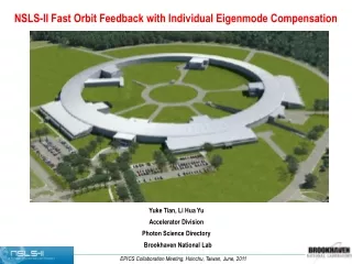
Orbit feedback system architecture FOFB calculation – compensation for each eigenmode • Fast orbit feedback system is a typical multiple-input and multiple-output (MIMO) system. For NSLS-II, there are 240 BPMs and 90 fast correctors. Tranditional singular value decomponsition (SVD) based FOFB treats each eigenmode the same. • The reality is, a MIMO system will have different frequency response for different eigenmode and thus it is desirable to design different compensation to each eigenmode. • The challenge is to finish the large computation within the time budget of FOFB system. • NSLS-II FOFB system takes advantage of our two-tier communication structure and the parallel computation capability of FPGA to do the compensation for each eigenmode in FPGA. EPICS Collaboration Meeting, BNL, 2010
Orbit feedback system architecture • A simple SISO feedback system Controller C(z) Plant H(z) EPICS Collaboration Meeting, BNL, 2010
Orbit feedback system architecture • Fast orbit feedback system algorithm (MIMO system) Compensator (PID etc) Controller R-1=VΣ-1UT Accelerator R=UΣVT R: response matrix R-1: reverse response matrix FOFB baseline algorithm Offline operation: kick each corrector measure all BPM and get response matrix R calculate R-1 with SVD (10KHz) operation: measure/distribute all BPM data calculate corrector setpoints set correctors EPICS Collaboration Meeting, BNL, 2010
Orbit feedback system architecture • FOFB baseline calculation For each corrector plane • Each of the corrector setpoint is calculated from a 1xM vector and Mx1 vector multiplication. If 8 BPM/cell, M=240. EPICS Collaboration Meeting, BNL, 2010
Orbit feedback system architecture • Problems for baseline algorithm • The ill-conditioned response matrix will cause numerical instability • Solution: 1) Truncated SVD (TSVD) regularization: sharp cut off • 2) Tikhonov regularization For each corrector plane • Each of the corrector setpoint is calculated from a 1xM vector and Mx1 vector multiplication. If 8 BPM/cell in NSLS-II, M=240. Total: ~240 MAC. EPICS Collaboration Meeting, BNL, 2010
Orbit feedback system architecture EPICS Collaboration Meeting, BNL, 2010
Orbit feedback system architecture EPICS Collaboration Meeting, BNL, 2010
Orbit feedback system architecture • Problems for baseline algorithm • To suppress high frequency contribution to the integrated amplitude, it is desirable to compensate each mode in frequency domain . So far, all the FOFB has an assumption that each mode has the same frequency response (same bandwidth). Accelerator R=UΣVT Qi(z-1) UT V Compensation for each eigenmode EPICS Collaboration Meeting, BNL, 2010
Orbit feedback system architecture • Calculation with the compensation for each mode :eigentspace components of : Compensator for mode i. EPICS Collaboration Meeting, BNL, 2010
Orbit feedback system architecture • Calculation with the compensation for each mode • 1. Calculate the eigenvector components (d1,d2,…dN) for BPM displacement • Total calculation: 1xM vector times Mx1 vector. Do this N times (for each ). This is N times larger calculation than gain-only FOFB calculation. For NSLS-II, N=90. Total MAC: 240 * 90 = 21,600 • 2. For each , design compensation . • 3. Output modes (V) times . 1xN vector times Nx1 vector. • Challenge: need to finish the calculation within a few microsecond. • FPGA is perfect for this task. It can carry out the calculation (Matrix calculation and DSP compensation) in parallel. EPICS Collaboration Meeting, BNL, 2010
Implementation of fast orbit feedback • Calculation with the compensation for one mode Dual Port RAM Select Active Eigenvector Eigenvector From control system MUX Dual Port RAM Eigenvector Compensation (PID, Notch filter etc) From control system X + Dual Port RAM BPM data From SDI link EPICS Collaboration Meeting, BNL, 2010
Implementation of fast orbit feedback • Single mode component compensation (floating point module) EPICS Collaboration Meeting, BNL, 2010
Implementation of fast orbit feedback • Single mode component compensation (floating point module) Simulated BPM data Single mode component Simulated input matrix Single mode component with compensation EPICS Collaboration Meeting, BNL, 2010
Implementation of fast orbit feedback • Single mode component compensation • (compare fixed point and floating point module) EPICS Collaboration Meeting, BNL, 2010
Implementation of fast orbit feedback SystemGenerator: floating point with fixedx point EPICS Collaboration Meeting, BNL, 2010
Implementation of fast orbit feedback • Single mode component compensation • (compare FPGA fixed point and Matlab floating point calculation) Calculation difference for single mode component Calculation difference for single mode component with compensation EPICS Collaboration Meeting, BNL, 2010
Implementation of fast orbit feedback • Single mode component compensation • (FPGA hardware co-simulation and Matlab floating point calculation) EPICS Collaboration Meeting, BNL, 2010
Implementation of fast orbit feedback Compare FPGA hardware co-simulation results and Matlab floating point calculation EPICS Collaboration Meeting, BNL, 2010
Implementation of fast orbit feedback Flexible frequency compensation in FPGA for each eigenmode 60Hz notch filter 200KHz low path filter EPICS Collaboration Meeting, BNL, 2010
Implementation of fast orbit feedback • Calculation for corrector setting (one plane) EPICS Collaboration Meeting, BNL, 2010
Orbit feedback system architecture Corrector setpoint to power supply system Master (PSC master, Cell controller) PSC PSC PSC PSC TX RX TX RX TX RX TX RX RX TX RX TX RX TX RX TX RX TX RX TX TX RX TX RX PSC PSC Power supply SDI link RX TX RX TX Redundant 100Mbps link to deliver FOFB calculation results (corrector setpoints) to PSC Dynamic ID assignment Flexible package size Simply cabling between PSCs and cell controller. TX RX PSC PSC PSC PSC TX RX TX RX TX TX RX RX RX TX RX RX TX TX EPICS Collaboration Meeting, BNL, 2010
Progress BPM – finished first revision RF signal inputs 4 ADC channels V5 FPGA 256MB DDR2 SFP for fiber SDI link GigE to EPICS IOC EPICS Collaboration Meeting, BNL, 2010
Progress Cell Controller – finished first revision 12 50Ohm TTL outputs 16 isolated TTL inputs 4 analog outputs 2 PS SDI links 256MB DDR2 V5 FPGA SFP for fiber SDI link GigE to EPICS IOC EPICS Collaboration Meeting, BNL, 2010
Progress Power supply controller – in production 3 6 4 1 7 7a 8a 5 2 8b 1 = JTAG connectors – Programming to FPGA and CPLD. 2 = RS232 port – Communication to PC for diagnostic and software development. 3 = DDR2 memory modules – PS diagnostic data, CPU memory. 4 = SDI connectors – Communication between PSC master (or cell controller) and PSC slaves. 5 = Fiber transceiver – Communication with PSI. 6 = Ethernet connector – Communication to EPICS IOC for PSC master. 7 = FPGA (Spartan3A) 8 = CPLD(8a) & SPI memory(8b) – Dual boot and remote programming functions. EPICS Collaboration Meeting, BNL, 2010
Progress • BPM hardware (DFE and AFE) passed the first revision. The second revision is underway. • Cell controller (DFE and IO board) passed the first revision. • BPM FOFB data measurement is tested with lab simulated data and real beam data. • BPM FOFB data delivery (fiber SDI link) is tested. • FOFB calculation is tested. • Power supply SDI link is tested. • Power supply controller is in production. • We are working on the FOFB system integration. It includes integration of BPM, cell controller and power supply controller units. EPICS Collaboration Meeting, BNL, 2010
Summary • NSLS-II tow tier structure provides fast and deterministic data transfer for BPM data (BPM to cell controller), and power supply setpoints (cell controller to power supply controller). Cell controller is the central data concentrator/generator that has all the necessary data for FOFB calculation and needs no extra data shuffling. All BPM and power supply data bits are put “on wire” once. • NSLS-II FOFB is taking advantages of the two tier structure and the parallel computation capability of FPGA to implement a unique FOFB algorithm that can carry compensation for each eigenmode. NSLS-II will be the first facility to implement such FOFB approach. • NSLS-II FOFB hardware, firmware and software design will be fully open to the community. For more hardware and firmware details, please go to tomorrow’s “Open Hardware Development Workshop”. EPICS Collaboration Meeting, BNL, 2010
Acknowledgments • FOFB algorithm • Lihua Yu • Igor Pinayev • BPM/ Cell controller development • Kurt Vetter • Joseph Mead • Joseph De Long • Kiman Ha • Alfred Dellapenna • Yong Hu • Guobao Shen • Om Singh • Bob Dalesio • PSC and PS design • Wing Louie • John Ricciardelli • George Ganetis EPICS Collaboration Meeting, BNL, 2010