Download

1 / 23
230 likes | 249 Vues
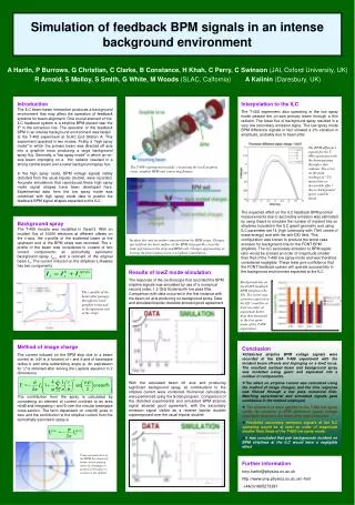
Introducing an innovative beam position measuring device for accelerators, with high precision and integration capabilities within the Elettra Control System. The system aims for sub-micron spatial resolution, stable performance, and compatibility with existing accelerator interfaces. Test validated in real-world conditions for seamless integration.

E N D
Integration of a novel BPM system within the global orbit feedback environment of Elettra R. De Monte, G. Brajnik,S. Cleva,S. Bassanese, G. Cautero Thanks to G. Gaio for his G.O.F. support
Introduction to a eBPM Elettra project Goal of the project is the development of the prototype of an innovative device for measuring beam position, for rings such as Elettra, Elettra2 and single-pass machines such as Fermi A measurement system consisting of a RF section, an FPGA-controlled ADC section able to detect the position of the beam with sub-sampling techniques and a section capable of performing high-level processing (position calculation, calibration, system communication control). Fully integrated in Accelerator Control Systems (Tango, Epics) and compatible with the "environmental" constraints required by these devices. Spatial resolution less than 1µ @100Hz Long term stability (24hrs) and beam current dependance (70% machine range) less than 4µ rms Communication through Gigabit Ethernet connections MODULAR SYSTEM: Stand alone FrontEnd, digitizer and timing system.
Replacing only ONE old BPM Electronics To validate the prototype for the project a test in a real environment, was required. The prototype has been integrated in the Elettra Control System. • System constrain / interfaces / signals: • Timing: • 1.156MHz pecl Storage Ring Clock “SRC” (RF/432) • Sync Signal to synchronize all the gigabit channels GOF (Global Orbit Feedback)note1 • Data: • Ethernet interface with Tango server data and house-keeping • Gigabit Ethernet interface for GOF data (UDP packets) note1: the signal is sent once a time and it is pre-triggered by a software command. It causes all units sending data to GOF inputs at ≈10KHz at the same time (phase) within 20µSec. note1: the signal is sent once a time and it is pre-triggered by a software command. It causes all units sending data to GOF inputs at ≈10KHz at the same time (phase) within 20µSec. 4
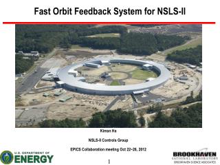
System Test block diagram design Win10PC With Labview, Quartus,RDP Linux Virtual machine ELETTRA SERVICE AREA Tango Server Elettra Control System FPGA CMDS and DATA ELETTRA TUNNEL Elettra Global Orbitfeedback GOF DATA CLK 4x150 Msamp 16 bit ADC Elettra Timing RF FrontEnd with pilot tone Dual PLL Low Jitter Clock SRC (machine clock) ElettraNetwork 5
FPGA block diagram Parallel data processing Carrier demodulation Pilot demodulation 6
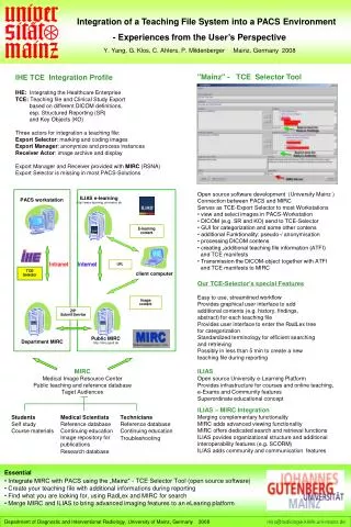
Architectural considerations • The main goal of this work was to prove that we are able to replace an existing BPM electronics. • For this reason we had to emulate the two connections to the control system. • Tango server : • For the Tango server , we made a porting of a standard Tango BPM server into the Linux virtual machine. The greatest difficulty of this work was to have the data read from the software module instead of the hardware directly. This is because the software module receive the data flow from one of the FPGA ethernet ports have to shares it with Tango server , AGC software module and Data Logger software module. • GOF (Global Orbit Feedback) data link: • A UDP packet is formed and sent to the GOF Section manager. It contains the pilot tone compensated position plus the mechanical to electrical BPM offset with respect to the quadrupole. This offset has been measured with BBA (Beam Based Alignment) system.
Linux VirtualMachine: data path and process structure Tango server UDP packet receiver process Elettra Control System network UDP data packets from FPGA Automatic Gain Control process eBPM RF Front End Legenda Gigabit Ethernet P2P Gigabit Ethernet network Data Logger process Interprocess communications (UNIX Socket) Terminal and filesystem 8
Synchronization of GOF data packets • The PLL is locked to the SRC clock • We program the PLL to pilot the ADC clocks with a fractional part of 500 MHz ≈150.7MHz • All the FPGA processing clocks are in phase with the Elettra machine clock • The ≈10KHz data rate is derived from 1.156 MHz • The exact frequency is fSRC / 116 = 9.9655 KHz… • …or not???? Of course not! Due to a different internal processing, the data rate that comes from Libera electron is slightly different (0,02 Hz) from 9.9655KHz 9
A simple workaround Use the exising already syncronized ethernet packet as a trigger BPM #7 To other 11 Elettra GOF sections ELETTRA G.O.F. section n (7) local central unit BPM #6 BPM #0 BPM #5 Elettra eBPM electronics BPM #4 BPM #3 BPM #2 BPM #1 10
Finalsystem Test block diagram ELETTRA SERVICE AREA Win10PC With Labview, Quartus,RDP Linux Virtual machine Tango Server ELETTRA TUNNEL Elettra Control System FPGA CMDS and DATA Elettra Global Orbitfeedback GOF DATA Libera BPM GOF DATA Trigger (eth) CLK 4x150 Msamp 16 bit ADC Elettra Timing RF FrontEnd with pilot tone ADC clock Dual PLL Low Jitter Clock SRC ElettraNetwork 11 11
Test the whole electronics in real environment Elettra Service Area FPGA and Gigabit Ethernet detail Elettra Tunnel 12
The Logger Output Started 18-2-2018 22:7:18 logging to file GofON_1min_mean60_quat.xlt Now 3 loglines 18-2-2018 22:10:21 Va = 43065835.4 RMS 21599.18 Vb = 51906701.7 RMS 27025.16 Vc = 55702573.9 RMS 25403.22 Vd = 46934320.0 RMS 29354.82 Sum = 197609431.1 RMS 14998.18 Q = -7236.0 RMS 691.59 Xum = -1754.591 RMS 10.09 Yum = -754.764 RMS 1.55 PVa = 53451318.7 RMS 1755.58 PVb = 54265351.1 RMS 1741.43 PVc = 53870777.4 RMS 1690.61 PVd = 53693140.5 RMS 1715.98 PSum = 215280587.7 RMS 5948.55 PQ = -58206.8 RMS 184.56 PXum = -90.701 RMS 0.18 PYum = 13.807 RMS 0.18 Compensated Xum = -1663.890 TangoXum = -771.690 Xoffset= 892.200 Compensated Yum = -768.571 TangoYum = 119.429 Yoffset= 888.000 att A 0= 4 1= 94 att B 0= 4 1= 94 att C 0= 4 1= 94 att D 0= 4 1= 94 att Pil 12 freq=502435897 Pil out1 4 out2= 9 TEMP abcdl: 405 407 401 385 412 With 20 mm Vacuum Chamber diameter
Troubleshooting using pilot Having a well-known pilot signal can help detect any hardware problems. Here is an example of "strange" behavior during an 8-hour acquisition. This is the cause of the strange behavior noted, found after a brief investigation. One of the four reference voltage signals ADC had a broken contact. So one of the four ADC voltage references was inside the ADC itself rather than the more precise and stable external one.
Temperatures logging Temperatures in 24 Hrs taken from the internal electronics of a eBPM RF Front End placed inside Elettra’s machine tunnel. Variations in the 24 hours are less than 0.4°C pk-pk
Conclusions A prototype of the new eBPM using “pilot tone” compensation technique has been successfully tested and used in Elettra machine. The test was in a real environment within a control system and Global Orbit Feedback, replacing one old BPM electronics. The measured “on field” performances for eBPM with 20mm chamber are: Resolution: <200nm @ 10KHz 8hrs stability: < 500nm This system has been in operations also with a users dedicated machine for more than 10 hrs. During these tests no packet loss, no software/firmware hangs or structural issues have been detected. During normal operations is possible to know the quality and the reliability of the measure simply monitoring the pilot tone position. Thanks to the pilot tone, a sneaky issue (one ADC reference voltage internal instead of external) has been discovered and fixed.
Clipboard – for copy and paste Text Box Text Text Text Text Text Text Text Text Text Text Box • Text Text Text • Text Text Text • Text Text Text Text Box Text Text Text Text Text Text Text Text Text Text Box • Text Text Text • Text Text Text • Text Text Text Rectangle Text Text Text Text Text Text Text Text Text Text Text Text Rectangle • Text Text Text • Text Text Text • Text Text Text