Download
1 / 26
260 likes | 399 Vues
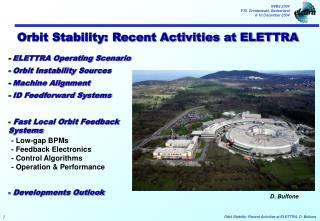
Orbit Stability: Recent Activities at ELETTRA. - ELETTRA Operating Scenario - Orbit Instability Sources - Machine Alignment - ID Feedforward Systems. Fast Local Orbit Feedback Systems. - Low-gap BPMs - Feedback Electronics - Control Algorithms - Operation & Performance.

E N D
Orbit Stability: Recent Activities at ELETTRA - ELETTRA Operating Scenario - Orbit Instability Sources - Machine Alignment - ID Feedforward Systems • Fast Local Orbit Feedback Systems - Low-gap BPMs - Feedback Electronics - Control Algorithms - Operation & Performance • Developments Outlook D. Bulfone
ELETTRA Operating Scenario - Insertion Devices: - Machine Operating Parameters: PM = Pure Permanent Magnet, HYB = Hybrid, EM = Electromagnetic SCW = Superconducting - 23 ID segments installed (6 APPLE-II) - All eleven long straights filled.
Orbit Distortion and Instability Sources - ground settlings and temperature fluctuations - thermal load on vacuum chamber: orbit shift up to 100/30 m H/V at ID center within 2 hours after the end of energy ramping (without any orbit correction or feedback) - ID gap changes: residual orbit distortion, not completely compensated by feedforward systems: <3-4 m rms on closed orbit and up to ~5 m at ID center after recalibration - mechanical vibrations: recently increased bump of components around 23 Hz, due to magnet cooling water flux: <10 m at ID centre horizontally - 50 Hz and its harmonics: from mains: power supplies, etc…: < 6 m for each component 0.01 Hz - 23 Hz Hor. mechanical vibrations of Q2_S2.2 quadrupole 0.1 Hz 1 Hz - Hor. & Ver. beam spectra at low-gap BPM, Section 2 10 Hz 100 Hz Frequency
P2P Corrected 200 µm Machine Alignment - Complete machine re-alignment, including insertion devices, was performed in January and August ‘04 shut-downs. - A laser tracker is used for magnet alignment. P2P 1.3 mm Radial displacement of Bending magnets before and after (blue line) alignment
Machine Alignment • Prior to machine re-alignment: machine was sensitive to orbit position: e.g., feeddown effects (tune shifts with amplitude) and coupling of x-y motion. • - Following the re-alignment: Tune and chromaticity changes with no orbit distortions, small corrector strengths, faster converging orbit correction, faster calibrations of ID correction coils. Vertical orbit and tune dependence on Horizontal orbit Before and After Re-alignment
ID Feedforward Systems - Closed orbit distortion created by ID gap/phase changes is compensated by feedforward systems based on two pairs of correction coils. - Correction coils look-up table values are obtained by off-line calibration for different gap/phase values, aimed at minimizing the rms of the difference orbit. - About 10 table entries/coil (10x10 for APPLE-II), linearly interpolated by the feedforward loop, which runs when the gap/phase change (from 2 to 10 Hz for the different ID cases). ID8.1, ph 0 -> 20 -> -20 -> 0 mm 5 μm 4.5 μm ID6, gap 150 -> 30 mm - Residual vertical orbit distortion measured by low-gap BPMs, not completely compensated by feedforward systems - Electromagnetic Elliptical Wiggler: - Feedforward system for the compensation of the EEW dynamic orbit distortions allows to change the radiation polarization in AC mode (trapezoidal, sinusoidal up to 100 Hz) with no measurable orbit perturbation.
Fast Local Orbit Feedback - Two LOF systems in routine operation during users shifts (Section 2 & 7) - Correct beam position & angle on both planes at ID centre - Use two low-gap BPMs and four corrector magnets - 8 kHz rate
Low-gap BPM 1 Low-gap BPM 2 Low-gap BPMs - Low vertical gap (14 mm), following the adjacent ID vacuum chamber profile + bellows 14mm - Mechanical movements monitored (<50 nm rms resolution) with respect to a Carbon fiber reference column (thermal expansion coeff. = 1.9 µm/ºCm): taken into account in the final beam position reading Contact-free capacitive sensors Carbon fiber reference column
Feedback Electronics VME Bus VA1 VB1 VC1 VD1 Digital Receivers RF Front End CPU PowerPC Board PCI Bus PMC 8 ch DAC 4 IF Signals VA2 VB2 VC2 VD2 8 Digital Receivers RF Front End 4 BPM Detector Digital Processing Interface to Corrector PS
Feedback Electronics Digital Receivers - BPM Detector: - RF Front-end translates RF signals to Intermediate Frequency (20 MHz). - RF02 from IT. - VME Digital Receiver (collaboration with SLS and IT) sampling at 62.5 MSample/s, 14 bits. RF Front-ends
Feedback Electronics PowerPC CPU board - Digital Processing: • Feedback digital processing algorithms executed at 8 kHz rate by a “standard” control system PowerPC (G4 at 400 MHz) CPU board • - GNU/Linux with real-time extension RTAI (Real Time Application Interface). No dedicated DSPs • Same CPU board performs feedback supervision, 8 kHz data acquisition and executes the usual TANGO control system tasks.
Feedback Electronics - Real-Time Performance Figures: - Latencies of an Interrupt Service Routine and of a thread triggered by a VME interrupt under Linux/RTAI [Executed on the PowerPC CPU board in a heavily loaded configuration] - Context switching time between two threads [Executed on the same hw/sw configuration]
Corrector PS setting signal DC DAC 16 bits Analog Sum Feedback DAC 16 bits Feedback Electronics PMC DAC mezzanine - Interface to Corrector Power Supplies: - The same corrector magnets/power supplies normally used for ‘standard’ DC orbit correction are also employed by the fast feedback system. - The corrector power supply set point is obtained as the sum of the signals generated by the ‘standard’ DC DAC (16 bits) and the feedback DAC (16 bits), which acts on a reduced current range. - 8 channel PMC DAC mezzanine plugged on the CPU board
Control Algorithms - System Dynamics: - Dynamic behavior dominated by corrector magnet + power supply: - 3dB cut-off frequency of 70 Hz. - Negligible phase delay induced by eddy currents in stainless steel vacuum chamber: 1deg@60Hz, 2deg@100Hz. Measured open-loop system frequency response, fit by a 3rd order polynomial in z. 70 Hz
Control Algorithms - The PID: - The PID: Block diagram of the model used to simulate closed-loop response. - Delay from BPM to corrector DACs is 330 μs. - Low Pass Filter limits input signal dynamics to avoid non-linearities of corrector power supplies: cut-off frequency 150 Hz. - Closed-loop frequency response with PID (KP=3, KI =0.01, KD=10): - 3dB point at 150 Hz. -3 150 - The Harmonic Suppressors: - Remove specific periodic components, like those induced by the mains (50 Hz and harmonics). - Digital resonator placed in the loop acts as a notch filter if the open loop phase rotation at the resonance frequency is 360º - Run in parallel to the PID
- To avoid saturation, a slow loop runs every minute and transfers, through the control system, the mean values of the LOF DACs to the DC DACs. Operation & Performance - LOFs activated at the end of injection + ramping procedure, after orbit correction at all ID and bending source points. - Corrected horizontal/vertical position values at low-gap BPMs taken as set point by LOFs. - Periodic orbit correction disabled in the corresponding ID straight sections. - Given the reduced range of the corrector current available for the LOFs, significant orbit drifts may saturate the feedback DACs. • - Mean values of the four LOF vertical corrector currents while opening/closing the gap of some IDs (LOF ON). [s]
Operation & Performance - Beam Position Spectra (1): - Horizontal and vertical beam position spectra measured by a low-gap BPM: • LOF OFF (blue) • LOF ON with PID only (green) • LOF ON with PID + HS at 50, 100, 150, 200, 250, 300 Hz (red) Vertical Horizontal
Operation & Performance - Beam Position Spectra (2): - Horizontal photon beam position spectra measured by photon BPM: • LOF OFF (blue) • LOF ON with PID + HS at 50, 100, 150, 200, 250, 300 Hz (red)
Operation & Performance - Time Domain Measurements: LOF OFF LOF OFF LOF ON LOF ON Horizontal Vertical Horizontal (left) and vertical (right) beam position measured by a low-gap BPM with LOF OFF / ON (8 kHz acquisition rate, low-pass filtered at 250 Hz) - rms of position and angle of source point at ID centre over 8-hour period with LOF ON, calculated from the two low-gap BPM readings: [8 kHz BPM acquisition rate] [20 Hz BPM acquisition rate]
Operation & Performance - Beamline Measurements (1): • - Mirror current with LOF OFF/ON • (one measurement every 3 s) • - With PID + 5 Harmonic Suppressors, noise reduced from about 1.2% to 0.3% - Measurements taken at different values of the stored electron beam current. • - Effect of ID 3, 8 and 9 gap movement • - Mirror current with LOF OFF/ON during spectrum scan (one measurement every 13 s, 25 min total period) • - Measurements taken at different values of the stored electron beam current.
Operation & Performance - Beamline Measurements (2): • - First Harmonic of the Undulator Spectrum with LOF OFF (blue) and ON (red). • - Zoomed first Harmonic of the Undulator Spectrum with LOF OFF (blue) and ON (red).
Operation & Performance - A Beam Position Monitoring Tool (1): - Histogram of the electron beam xy position (320 position samples at 8 kHz, refreshed at 25 frames/s) - Beam position monitoring & FFT, refreshed at 25 frames/s - LOF is OFF.
FEEDBACK OFF Operation & Performance - A Beam Position Monitoring Tool (2): • - Real-time observation of the LOF effect. • - PID (KP=3, KI=0.01, KD=5) + 5 Harmonic Suppressors at 23, 50, 100, 150 and 200 Hz FEEDBACK ON
Developments Outlook - LOFs do not stabilize orbit at bending magnet sources - Cross-talk between many LOFs (not measurable now) could become an issue. Fast Global Orbit Feedback: - Use (potentially) all existing rhomboidal BPMs equipped with state-of-art detectors (implies upgrade of all BPM electronics) - 12 feedback substations (1 per sector) connected by a real-time “reflective memory” network, sharing all BPM readings and correction values - Existing LOF stations already designed to be integrated in the GOF architecture - Full Energy Injector: - A full energy Booster injector, allowing top-up mode, is under construction.
Thanks to the following Groups: • - Alignment, Metrology and Thermal Loads • - Controls • - Insertion Devices • - Instrumentation • - Machine Physics