Recent developments in Geant4 related activities at CENBG
410 likes | 585 Vues
Recent developments in Geant4 related activities at CENBG. Sébastien INCERTI (IN2P3/CENBG). 13-19 September 2007 Hebden Bridge, UK. 12th Geant4 collaboration workshop.

Recent developments in Geant4 related activities at CENBG
E N D
Presentation Transcript
Recent developments in Geant4 related activities at CENBG Sébastien INCERTI (IN2P3/CENBG) 13-19 September 2007 Hebden Bridge, UK 12th Geant4 collaboration workshop
Sorry for not being with you this year, important commitments tomorrow at Bordeaux University and early next weekI will try to be as understandable as possible
Contents • Four simulation projects • Ray tracing for nanobeam line design • The Geant4 DNA project • A mission to Mars • ( 3D phantoms for microdosimetry ) • Other important information
Ray tracing simulations • Collaborators • Fredrik Andersson, PhD, Bordeaux1 Univ. • Geoff Grime & Michael Merchant, Surrey Univ., UK & Oxford Microbeams Ltd. • The CENBG nanobeam line configuration has been entirely designed thanks to Geant4 • Construction is still in progress • first focusing doublet stage is now in place • second focusing triplet stage under construction • alignment phase will start right after
Status • New beam emittance measurements performed on the Singletron accelerator for a better modelling of the incoming beam • New analytical 3D quadrupole field model, more precise than a 3D mesh (presented last year at Geant4 2006 collaboration workshop) • Expected transmitted current • Deflection plates near target optimized ; • beam deformation when deflected • ripple studies • Results will be presented next week at Ion Beam Analysis 2007 conference series
Beam emittance modelling • Purpose : model precisely the beam transverse position distribution (x, y) and angular distribution (q, f) at the nanobeam line collimator object • Since the nanobeam line is not operative yet, we have measured the beam emittance at the entrance of the microbeam line using a set of vertical and horizontal slits and deflection plates.The beam has then been repropagated towards the nanobeam line object Future NANOBEAM line for IBA (PIXE, RBS, STIM) MICROBEAM line for Cellular irradiation and IBA (PIXE, RBS, STIM)
Comparison experiment/model q or f C0 Measured emittance retropropagated to nanobeam line object Model based on A rescaled 3rd order polynomial function + gaussians X or Y
Emittance propagation with Geant4 along nanobeam line IM C0 CA I CB
Quadrupole field models • Nanobeam line consists of a doublet and a triplet of OM-50 quadrupoles (length : 100 mm, inner radius : 7.5 mm) • Last year we presented a 3D mesh model of a single quadrupole, computed thanks to the OPERA suite software • Advantages : • More realistic than a classical square field model • Modelling of fringing fields on quadrupole edges • Drawbacks : • Granularity not high enough for ray tracing with parallax rays • 1 mm3 • Solution : develop an analytical model of the quadrupole magnetic field based on Enge’s formalism and valid for all angular divergences
Field models Transverse Bx or By component Longitudinal Bz component
Intrinsic aberration coefficients Spherical intrinsic aberration increase (larger spiral force by Bz)
Grid shadow imaging • A widely used method to measure the aberrations coefficients of a certain quadrupole system. • The method gives image coordinates from a grid placed at the image-plane and the corresponding divergence coordinates from a grid shadow pattern, cast on an ion luminescent screen placed a couple of hundred millimetres downstream. Electrostatic deflection TRIPLET DOUBLET Luminescent screen Grid 250 Image plan 300 500 mm
Examples of grid shadow images Parasitic rotation (0.1 deg) of the last quadrupole Perfect system with intrinsic spherical aberration only ~10h of CPU Same tilt is present but with an added rotation (0.1 deg) of the first magnet in the triplet Forward tilt (0.01 deg) of the last magnet
Deflection plates • Modeling of the electrostatic scanning plates with Geant4 • Changing the length ratio between x and y scanning plates in order to find the optimum scan size for a given voltage under the conditions • scanning plate system total length equals 52 mm • gap between plates should be greater or equal to 4 mm • The resulting model of the scanning plates was used to investigate the effect on beam size and shape from voltage ripple and deflection. • Ripple • uniform randomized ripple of 80 mVolt peak to peak set on each plate • 1 MeV proton beam of 50 × 30 nm FWHM • 37 % and 93 % broadening in x and y planes respectively • Deflection • 400 µmin both planes with 2000 ∆V between the plates • 3 MeV proton beam • 7 % and 15 % broadening
Future • Short term • These results will be published this autum in NIM • We have so far 4 papers published for this project • Will be proposed as a Geant4 advanced example • Mid-term : when the nanobeam line is operative • New emittance measurements on the nanobeam line • Comparison of measured performances and Geant4 predictions
The Geant4 DNA project • Collaborationof S. Chauvie, S. Incerti, P. Nieminen, P. Moretto, M. G. Pia • Main objective : prediction of DNA damages (double strand breaks – fatal lesions -, DNA fragments…) after irrradiation of cells, taking into account realistic DNA models • Physics models paper submitted to TNS, review still in progress • I’m currently finalizing the final states generation for all processes before committing to CVS (electrons, protons, alphas and their charge states) • Expect the full package to be ready for the December release • Urgent need for collaborators ; a new form of collaboration ? • IN2P3 will support this activity
Future of DNA project • Short term • Finish final states • Speed issues • Test DNA in our voxellized cellular phantoms • Cell survival advanced example • Long term • Chemical phase • DNA geometry • Biological damage stage • Open to any low energy electromagnetic extension of Geant4 • Other materials than liquid water for Physics models : DNA basis, Si for space applications • Test on Grids ?
A mission to Mars l = 25 mm H = 1mm L = 75 mm • Collaborators • Aurélie Le Postollec, PhD, Bordeaux Univ. • Giovanni Santin, Petteri Nieminen, ESA/ESTEC • Laurent Desorgher, Bern Univ. • Lewis Dartnell, Oxford Univ. College • Development of a biochip • a miniature sampling method allowing identification of biological molecules (biomarkers) for the detection of traces of life in the solar system • recognition using specific fluorescent molecules (ligands) fixed on a plate • Need to test the biochip recognition capabilities using irradiation facilities • Experimental irradiation conditions must be determined in order to be as close as possible to the radiation environment encountered during the mission • We use Geant4 in order to simulate this environment : • In situ, on Mars ground (achieved) • During travel Earth Mars (in progress)
On Mars ground • Question : how to simulate the irradiation of a biochip a few cm2 in surface on Mars ground using cosmic spectra generated on top of the Mars atmosphere ? • Solution : we have created an interface between two useful tools : PLANETOCOSMICS and GRAS. This interface uses ROOT classes in order to shoot GRAS primary particles from PLANETOCOSMICS spectra. • More precisely : • Primary particles from CREME96 generated on top of atmosphere • GCR : H, He, C, O • SPE : H, He (worst week scenario) • Atmosphere (Mars-Gram) and soil (Pathfinder-Sojourner) modeled from PLANETOCOSMICS • Secondary spectra extracted on ground • Inserted into GRAS after proper normalization • Simple rover geometrical model and dose calculation • During travel : primary spectra are inserted directly into GRAS
Biopuce mass ~4,4g Total fluence on Mars ground • Generated by GCR H, He, C & O primaries • Physics list : • - standard EM • - QGSP_BIC_HP Dose in biochip = ~36 Gy in one month
Cumulated individual spectra Neutrons Deuterons Electrons Protons GCR + SEP GCR Positrons Alphas Tritons Gammas Ion z=4 Ion z=3 Ion z=5 Nb particles/cm²/s Ion z=6 Ion z=7 Ion z=8 T (MeV)
Integral neutron flux on ground Evaporation peak neutrons/cm²/s GCR + SPE worst week GCR
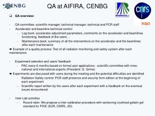
Experimental irradiation of biochip on AIFIRA facility • 96 h of AIFIRA beam time mid-October • Neutron effects never investigated • Among the dominant species on ground after gammas • Verification of antibody + fluorophore recognition and fluorophore resistance • Lyophylized samples or in solution • 4 orders of magnitude in absorbed dose • D in one month on Mars ground, 10 D, 102 D, 103 D (just to be safe…) • Two energies : 0.6 MeV and 6 MeV
Neutron production Solid target Two energies separated byoneorder of magnitude Gas target 0.6 MeV 6 MeV
Incident n spectra generated with Geant4 Neutrons are generated in Geant4 from published differential cross section and production energy tables Emission energy Emission angle Energy (MeV) Energy (MeV) Angle (deg) Angle (deg) D(d,n)3He for Td=2.8 MeV
Simulated irradiation setup for flux calculation n source q d • Fluxes on biochip calculated by two methods : • « Analytical »simulations • Cross section in biochip solid angle calculated from • « Monte Carlo »: Geant4 simulations shooting individual neutrons from source HTA horizontal plate 75.3 (l) x 24.9 (L) mm2
n source Irradiation duration q d HTA horizontal plate 75.3 (l) x 24.9 (L) mm2 • 0.6 MeV: 7Li(p,n)7Be for Tp=2.3 MeV • d = 10 cm, q = 40° • sW/stot=0.024 F = 8.1 107 n/s • Duration to reach D ( 1 month) ~ 1.4s • 10D 14s, 10²D 2min20s, 103D 23min20s • 6 MeV : D(d,n)3He forTd=2.8 MeV • d = 10 cm, q = 20° • sW/stot=0.017 F = 9.4 105 n/s • Duration to reach D ( 1 month) ~ 57 s • 10D 9min30s, 10² D 1h35min, 103 D 15h50min
An increasing local collaboration • Coussot Gaëlle, IBMM, UMR5247, chemist post-doc • Dobrijevic Michel, LAB, UMR5804, OASU, astrophysicist • Geffard Michel, IMS UMR5218, biologist • Incerti Sébastien, CENBG, physicist • Le Postollec Aurélie, LAB, UMR5804, OASU, PhD physicist • Moretto Philippe, CENBG, physicist • Trambouze Odile, IBMM UMR5247, bio-chemist
Future • Short term • Geant4 simulation of n irradiation experiment taking into account a detailed geometry of the irradiated samples • Realistic CAD model of rover & spacecraft from EXOMARS mission (Fastrad conversion to Geant4) • Realistic trajectory model from PHOENIX mission ? • Mid-term • Hadronic models > 10 GeV/n in PLANETOCOSMICS • Long term • A proposal submitted in 2008 to CNRS for a first biochip / dosimetry test aboard ISS
We will organize a Geant4 tutorial in France every year Supported by IN2P3 & CEA Local organizing committee : S. Cavata, S. Incerti, M. Maire, M. Verderi A different form ? (building a full example from scratch) Dates & place not selected yet An annual tutorial in France
Other teaching activities • One day Geant4 tutorial at theDo-Son school on Advanced Computing and GRID Technologies for Research (CNRS/Vietnam) • Institute of Information Technology, VAST, Hanoi, Vietnam, 5-16 November 2007 • Organizers : V. Breton (IN2P3), B. Mely (CNRS), T. A. Ngo (IoIT) • Geant4 is now part of an official university cursus (Master Recherche 2 – Astroparticles and Nuclear / Particle Physics) at Bordeaux 1 University from this year
A web site • http://geant4.in2p3.fr • New look in progress (CNRS requirements) • IN2P3 collaborators • Tutorial information • Download freely VMware tools and files
A new KEK-IN2P3 collaboration • Collaboration around Geant4 activities • Funded for 2007 & 2008 by KEK & IN2P3 • Topics • Education applications • Biology, Medicine & Space (DNA, hadrontherapy, biochip…) • GRID • We need to organize our first workshop
KEK & IN2P3 teams • 12 collaborators (researchers + engineers) • Members of the Geant4 or GATE collaborations