Download
1 / 31
310 likes | 429 Vues
Learn the assembly language programming and design of a simplified CPU with 11 instructions, 16-bit RAM, and key registers. Explore data transfer, fetch-and-execute cycle, instruction set, and more. Enhance your knowledge of CPU design concepts.

E N D
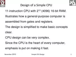
Design of a Simple CPU 11-instruction CPU with 212 (4096) 16-bit RAM. Illustrates how a general-purpose computer is assembled from gates and registers. The design is simplified to make basic concepts clear. CPU design can be very complex. Since the CPU is the heart of every computer, emphasis is put on making it fast. Simple CPU Design
The Register Set • A CPU is a sequential circuit • repeatedly reads and executes an instruction from its memory • fetch-and-execute cycle • A machine languageprogram is a set of instructions drawn from the CPU instruction set • Each instruction consists of two parts: an opcode and an address Simple CPU Design
11 instructions require a 4-bit opcode. • 12 bits of the 16-bit word remain for addressing 212 = 4096 16-bit words of the RAM. • The CPU has 8 special registers: • 16-bit accumulator(AC) • 12-bitprogram counter (PC) • 4-bit opcode(OPC) • 12-bit memory address register (MAR) • 16-bit memory data register (MDR) • 16-bit input register (INR) • 16-bit output register (OUTR) • 1-bithalt register (HLT) Simple CPU Design
The Registers Data Transfer in the CPU Simple CPU Design
The Fetch-and-Execute Cycle • Fetch-and-execute cycle has two portions • Fetch portion is always the same: • instruction, whose address is in the PC, is fetched into the MDR • opcode portion of this register is copied into the OPC • At this point the action of the CPU • diverges, based on the instruction in OPC Simple CPU Design
Suppose OPC is a load accumulator instruction. • the action required is to copy the word specified by the address part of the instruction into the accumulator • load accumulator is decomposed into 8 microinstructions executed in 6microcycles Simple CPU Design
The Instruction Set Simple CPU Design
Other operations can be performed using this set: • subtraction is realized with ADD, CMA, and 2’s comp • multiplication is possible through the use of CIL and ADD • multiple CILs can be used to rotate right one place, hence division is also possible • AND and CMA are complete Boolean system, hence every Boolean function can be realized by this machine if it is designed to address enough memory locations Simple CPU Design
This is a direct memory instruction • Addresses refer directly to memory locations containing the operands(data) on which the program operates • CPUs have also indirect memory instructions • Instructions in which an address is interpreted as the address at which to find the address containing the needed operand • CPU does two memory fetches • the first to find the address of the operand • the second to find the operand itself Simple CPU Design
Assembly-Language Programming • Instructions stored in memory consist of 16 bits. • the first 4 are opcode and the last 12 are address • It is hard to interpret such machine-languagestatements. • mnemonic opcodes and assembly languages are devised • Assembleris a program translating an assembly languageprogram into a machine language. Simple CPU Design
Example: a Boot Program Assembly-language program to boot up a computer is reading another program provided through the input port and stores the new program (16-bit words) in memory just above Boot. When reading is finished (determined by 0 word),control is transferred to the new program by jumping to the first location above Boot. Simple CPU Design
0 1 2 3 4 5 6 7 8 9 Simple CPU Design
The 1st instruction following the ORG statement reads the input register value into the accumulator. The 2nd instruction jumps to address 10 if AC==0, indicating that the last word of the program being loaded has been written into the memory. The next executed instruction is in address 10; control is transferred to the second program. Simple CPU Design
If AC!=0, its value is stored (indirectly) at a address (value) stored at ADDR_2 memory address. On the first execution of this command the value stored at memory address ADDR_2 is 10. The content of the accumulator is therefore stored at location 10. The next 3 steps increment by 1 the value of ADDR_2 by placing its contents in the accumulator, adding the value in memory address ADDR_3 (=1) to it and storing the new value into memory address ADDR_2. Simple CPU Design
Finally, the accumulator is zeroed and a JZ instruction is used to return to address ADDR_1 (=0), the first address of the boot program. The indirect STA instruction is not supported by the simple computer, but can be simulated by a self-modifying subprogram. Though self-modifying programs are considered a bad programming practice to, itillustrates the power of self-modification and the advantage of having indirection in the instruction set of a computer. Simple CPU Design
Timing and Control We need to design circuits controlling the combining and movement of data. Assignment notation is introduced. Simple CPU Design
Register transfer notation uses these assignment operations as well as timing information to break down a machine-level instruction into microinstructions that are executed in successive microcycles. Simple CPU Design
microinstructions for the execute portion Simple CPU Design
Generating Control Signals Define control variables that control the movement of data between registers or combine the contents of two registers and assign the result to another register. Associate a control variable L(A,B) if a microinstruction results in the movement of data from register B to register A, denoted A ← B. L(OPC,MDR) = t3 : OPC is loaded with the contents of MDR when t3 = 1 Simple CPU Design
Associate a control variable L(A,B ⊙ C) if a microinstruction results in the combination of the contents of registers B and C with the operation ⊙ and the assignment of the result to register A, denoted A ← B ⊙ C. L(AC, AC+MDR) = cADD ∧ t6 : The contents of AC are added to those of MDR and copied into AC when cADD ∧ t6= 1. Simple CPU Design
Control of Accumulator Group together all the microinstructions affecting accumulator Derive control variables Simple CPU Design
Hardware Implementation 16 7:1 MUXes MUX 7:1 MUX 7:1 16-bit ALU ADD AND NOT 16-bit registers Simple CPU Design
Execution of MUX 7:1 MUX 7:1 ADD AND NOT Simple CPU Design
Execution of MUX 7:1 MUX 7:1 ADD AND NOT Simple CPU Design
Group together all the microinstructions affecting a given register Derive control variables Simple CPU Design
Group together all the microinstructions affecting a given register Derive control variables Quiz: What and how many MUXes are required? Ans: 16 MUXes of 2:1 Simple CPU Design
Group together all the microinstructions affecting a given register Derive control variables Simple CPU Design
Group together all the microinstructions affecting a given register Derive control variables Simple CPU Design