Download
1 / 29
310 likes | 545 Vues
Neutron induced light-ion production at 175 MeV @ The Svedberg Laboratory, Uppsala. Svenskt Kärnfysikermöte XXVIII KTH-AlbaNova, Stockholm, 12 November, 2008. Riccardo Bevilacqua Department of Physics and Astronomy Division of Applied Nuclear Physics Uppsala University.

E N D
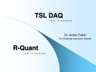
Neutron induced light-ion production at 175 MeV @ The Svedberg Laboratory, Uppsala Svenskt Kärnfysikermöte XXVIII KTH-AlbaNova, Stockholm, 12 November, 2008 Riccardo Bevilacqua Department of Physics and Astronomy Division of AppliedNuclearPhysics Uppsala University
The NEXT project • Neutron data Experiments for Transmutation • supported as a research task agreement by • Statens Kärnkraftinspektion (SKI)Swedish Nuclear Power Inspectorate • Svensk Kärnbränslehantering AB (SKB) Swedish Nuclear Fuel and Waste Management Co • Ringhalsverket AB 70% Vattenfall + 30% E.ON Ringhals Nuclear Power Plantlargest power plant in Scandinavia • started 2006-07-01
Background (for neutron induced cross sections at 175 MeV) • High-energy neutron applications: • Medical (e.g., C, O) • Cancer therapy with fast neutrons and protons • Dose estimation • Electronics (e.g., Si) • Single Event Effect caused by cosmic-ray neutrons • Accelerator Driven System (ADS) (e.g., Fe, Pb, U) • Benchmark of Nuclear Reaction Models Cosmic-rays + + + + + Silicon Chip +
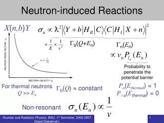
Neutron induced cross sections & transmutation techniques in ADS In a spallator coupled to a core: neutrons up to 1 GeV Present nuclear data libraries: up to 20 MeV Direct reactions models: work reasonably well above 200 MeV NEA nuclear science committee (A.J.Koning et al. 1998) high priority for transmutation applications cross section measurament of the (n,xp) reaction in the range 20 – 200 MeV for 56Fe, 208Pb, 232Th, 238U... Present status of light-ion production measurements: lack of experimental data in the 100-200 MeV region (< 100 MeV: Tohoku Univ. , LANL, Louvain-la-Neuve, Uppsala)
The current project • Extension of 96 MeV measurements using the new TSL neutron facility @ Uppsala within the framework of an international collaboration (Sweden – Thailand – Japan) • Double differential cross sections measurement at 175 MeV • C(n,x) (experiment in 2007, analysis in progress) • Fe(n,x) and Pb(n,x) (planned January 2009) • Comparison with theoretical model calculations and high-energy nuclear data file
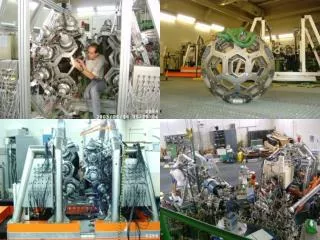
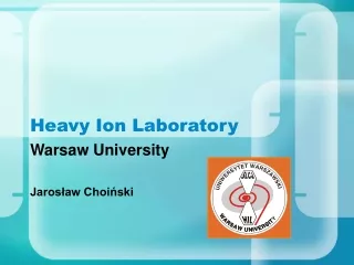
New neutron beam facility at The Svedberg Laboratory (TSL), Uppsala • Gustaf Warner Cyclotron • Proton energy ~180 MeV • Neutron source • Li(p,n) reaction • Quasi mono-energetic neutron source • Neutron energy 11-175 MeV
Shielding and collinator were studied and improved with use of MCNPX transport code
Experimental setup • MEDLEY • Detected light ions: p, d, t, 3He, α particle • Composed 8 ΔE-ΔE-E telescope • Angle: 20º -160º in step of 20º • ΔE detector: Si surface barrier semi-conductor detector • E detector: CsI(Tl) scintillator • Using ΔE-ΔE-E technique for particle identification 1000 μm
Experiment procedure • Neutron source • Li(p,n) reaction • Li target thickness: 23.5 [mm] • Proton beam energy: 178.7 [MeV] • Peak neutron energy: 174.3 [MeV] • Maximum proton beam current on target: 0.3 [μA] • Measurements • Target • Carbon (2007) • Iron (2007 and 2009) • Lead (2009) • CH2(n-p scattering peak used to normalize cross sections) • Empty frame (background)
Particle identification 1000 μm
Improvement of particle identification Thicker Si2 detector: 400-600 μm to 1000 μm The LIONS (Light Ions) Club 1000 μm
Conversion to absolute cross section Extract np elastic peak at 20º
Conversion to absolute cross section • Normalize • CH2 (n-p scattering peak) data is used to normalize the cross sections for C. • NP cross section data from NN cross section database (ref: http://gwdac.phys.gwu.edu) N: Number of counts in the peak M: Molecular mass t: target thickness [mg/cm2] Φ: relative neutron flux [n/cm2] Ω: solid angle from target to telescope [sr] NN cross section database Ref: http://gwdac.phys.gwu.edu
Proton production from Carbon at 175 MeV The LIONS (Light Ions) Club Masateru Hayashi, private communication (2008)(Kyushu University, from April 2008 Mitsubishi electric Co.)
Summary Measurament of double-differential cross section of (n,x) reactions on C at 175 MeV was done 2007. Additional iron shielding and thicker Si detectors will improve particle identification and reduce background. New measuraments on Fe and Pb are planned for January/February 2009. The LIONS (Light Ions) Club
Aknoledgment Masateru Hayashi, Kyushu University (Japan) Stephan Pomp, Uppsala University (Sweden) Vasily Simutkin, Uppsala University (Sweden) Udomrat Tippawan, Chiang Mai University (Thailand) Alexander Prokofiev, TSL Uppsala (Sweden) The LIONS (Light Ions) Club
Fast Neutron Therapy (1) Advantage of Fast Neutrons: high LET (Linear Energy Transfer) of the secondary particles created by neutron interactions.densely ionizing protons, alphas and heavy ion recoil products inflict a significant number of DNA double strand breaks. About 1.5 more double strand breaks (DSB) are observed after neutron irradiation than after photon irradiation of equal dose (*) (*) J. M. Cosset, M. Maher, and J. L. Habrand, "New particles in radiotherapy: an introduction“ Radiat. Environ. Biophys., vol. 34, pp. 37-39, 1995.
Fast Neutron Therapy (2) Typical survival curves for cells irradiated in 60Co and fast neutron beams under well-oxygenerated (exposed to air) and anoxic conditions. RBE (relative biological effectivness) and OER (oxygen enanchment ratio) values are given at the survival level illustrated (1 Gray = 100 rads) 60Co emits one electron with an energy of up to 315 keV and then two gamma rays with energies of 1.17 and 1.33 MeV, respectively. back
Single Event Effect Neutron induced soft-errors in microelectronics 000000000100000000 Single Event Effect (SEE) results stochastically from a single interaction between a device and an ionising particle. Neutrons, although not directly ionising, induce SEEs through nuclear interactions with constituent ions of the semiconductor lattice. Cosmic-rays + + + + + Silicon Chip + back
ADS and Transmutation (1) Transmutation aims at reducing the radiological impact of actinides and fission products in the high-level waste (HLW) by nuclear transformation of troublesome long-lived nuclides in strong radiation fields. The concept of accelerator-driven systems combines a particle accelerator with a sub-critical core
ADS and Transmutation (2) TRU (Transuranics): actinides with a higher Z than that of uranium MA: minor actinides back
aAt the entrance of the beam line to the user area. Flux measuredwith a monitor based on a thin-film breakdown counter (TFBC), utilising neutron-induced fissionof 238U with the cross-section adopted as neutron flux standard back (A. V. Prokofiev et al. Rad. Prot. Dos. 2007)
Quasi mono-energetic neutron source back (A. V. Prokofiev et al. Rad. Prot. Dos. 2007)
1. External ion injection: The external ion source can be used with axial injection into the cyclotron. An ECR source is used for a wide variety of ions (from alfa particles to Xenon). 2. The Cyclotron: Isochronous cyclotron for all particles except protons above 100 MeV. For protons in the range 100-180 MeV the cyclotron works as a synchrocyclotron. Particles and energies available. 3. Radiofrequency system: (System1 in figure) Two accelerating electrodes each covering an angle from 72 degrees at centre to 42 degrees at max. radius. Possible to use between 12.25 and 24.5 MHz (on the orbit frequency of the ions and on harmonics 2, 3 and 4). Two modes of operation: Fixed frequency (isochronous cyclotron) and Frequency Modulation (synchrocyclotron) Max. accelerating voltage 50 kV in fixed frequency mode and 16 kV when used in FM mode over a frequency band approx. 24-22 MHz. Max. power per system is 140 kW. 4. Vacuum system: Two large diffusion pumps with cryogenic baffles (and one smaller) combined with two cryopanels in the cyclotron chamber, giving a vacuum of approx. 10-7 mbar without gas load from internal ion source and 10-6 mbar with internal ion source. 5. QA1 and QA2 (Quadrupole magnets for focussing of the beam) 6. Internal Ion Source: Internal Penning Ionization sources are used for protons and some light ions (deuterons, alfa particles). 7. Sond 1: Measure the beam current. 8. Collimator: Used to reduce the beam size and the beam current. 9. BMA1 This bending magnet can switch the beam between the a-line and the b-line. Main data of the Gustaf Werner CyclotronSingle pole with three sectors for vertical focussingPole base diameter 2.8 m Pole gap hill-hill 0.2 m, valley-valley 0.362 m Magnet yoke (iron) weight 600 tons Copper coil weight 50 tons, power consumption max. 300 kW 13 sets of radial gradient field correction coils and two sets of harmonic correction coils Max. average field 1.75 T at a max. useful radius of 1.2 m Bending limit K= 192 Q2/A MeV Focussing limit (protons) 100 MeV, avoided by using frequency modulation up to 180 MeV back