Dynamic Scheduling
Dynamic Scheduling. Pipelines rely on instruction flow as scheduled by the compiler (whether optimized or not)

Dynamic Scheduling
E N D
Presentation Transcript
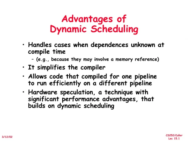
Dynamic Scheduling • Pipelines rely on instruction flow as scheduled by the compiler (whether optimized or not) • We could continue to fetch instructions as scheduled by the compiler, but we could use hardware to anticipate problems and dynamically schedule the instructions to the execution units (here, referred to as functional units) • This was the approach taken in the CDC 6600 in the late 60s, using a new piece of hardware called the scoreboard • The ID unit has an additional duty • issuing the instruction to the proper functional unit when the circumstances permit it • The scoreboard keeps track of the waiting and executing instructions, monitoring data dependencies and structural hazards • this leads to out-of-order completion of instructions, but as long as data dependencies are maintained, this is only a problem when we have exceptions (we’ll worry about that later)
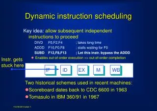
Example to Motivate the Scoreboard • Consider the following code: • L.D F0, 0(R3) • MUL.D F2, F0, F10 • ADD.D F4, F2, F12 • DIV.D F6, F8, F14 • In the MIPS FP pipeline, we have a data hazard after the L.D resulting in a stall and a data hazard after the MUL.D resulting in 6 stalls • The ADD.D cannot move into A1 until F2 has been forwarded out of MUL.D’s M7 stage, thus the ADD.D stalls for 6 cycles in ID and DIV.D stalls for 6 cycles in IF • There is no need for the DIV.D to stall since it is not data dependent on previous instructions, but there is a structural hazard in that ID cannot permit DIV.D to move into it while ADD.D is waiting • The scoreboard gets around such problems
The New MIPS Pipeline • The IF stage is the same • The ID stage is now broken into a two stages: decode/issue and read operands • Decode/issue decodes the instructions and tracks data dependencies, and manipulates the scoreboard • It then passes the instruction onto the proper functional unit for execution • Read operands is moved to the functional units to obtain register values right from the register file, or from functional units that forward their results • Functional units will write directly to the register file thus performing the WB step We might have additional FUs such as another FP + or FP * as needed
Issuing Logic • Given an instruction, examine its • Source registers – do either values need to be forwarded from other FUs? • Destination register – does the result get forwarded to another FU? • here, we have to be aware of WAW and WAR hazards • Instruction type – is a functional unit available? • If a functional unit is available and no other active instruction has the same destination register, then issue the instruction • If another instruction has this destination register, then it creates a potential WAW hazard • If either no functional unit is available or a WAW hazard exists, we postpone issuing this instruction which results in stalling the pipeline • but notice that we no longer stall the pipeline for situations that should not require it like the prior example
WAW and WAR Hazards • In the 5-stage pipeline, the only type of data hazards was the RAW hazard (read after write) • LD R1, 0(R2) • DADDI R3, R1, #1 • we are supposed to read R1 after we write R1 but because of where LD accesses the data cache, if we didn’t prevent it, we would read R1 in DADDI’s ID stage before the LD could write to R1 • The WAW hazard is a write after write – the writes occur in the wrong order • This is only possible if we permit out of order completion, but that is necessary when we introduce floating point, multiply and divide operations to the 5 stage pipeline • The WAR hazard is a write after read but performed in the wrong order because the read has been postponed • This can happen with the scoreboard • We’ll visit a WAR example in a little bit, after we explore how the scoreboard works
Scoreboard Structure • The scoreboard is a data structure which maintains three types of information • Instruction status (which stage issued instruction is in) • Functional unit status (for each functional unit, its status, where its destination and source registers are from, and boolean flags to indicate whether the source values are available yet) • Register result status (for each register, which functional unit might be writing to it) • a
How the Scoreboard Works • IF stage – same as in the pipeline, just fetch next instruction • Issue stage – take instruction from IF stage • If functional unit is not busy and destination register does not have a pending result (WAW hazard) issue instruction • Busy ‘yes’ • OP operation, • Fi destination register, Fj/FK source registers • Qj/Qk functional unit producing the source registers (if any) • Rj/Rk ‘yes’/‘no’ depending on whether source value is available yet • Result register for Fi functional unit name
Continued • Read operands • Occurs at the functional unit when Rj & Rk are set to yes • Rj/Rk ‘no’, Qj/Qk 0, Fj/Fk values • Execution takes place in the functional unit • Execution complete is set to true when functional unit completes execution • Write result • This step takes place after execution is complete and after any potential WAR hazard goes away (because of a read taking place elsewhere) • This stage takes a cycle by itself, so it happens the cycle after execution completes • Result register result, busy ‘no’, functional unit becomes available
Given the code under the instruction list with the following assumptions: Execution time in cycles: Add = 2 Multiply = 10 Divide = 40 Register write and register read of same register occur in separate cycles Only 1 FU can read operands at a time FUs: 1 int unit, 1 FP div, 2 FP Mult, 1 FP adder Example
Continued • During cycles 2-4, second L.D cannot issue because it also requires the same Integer functional unit, so the scoreboard just tracks the one L.D as it goes through read operands, execution and write result stages
Continued • Example continues: • Second L.D is issued • MUL.D is issued while L.D reads operands • SUB.D is issued while L.D executes the load but MUL.D cannot yet read operand F2 (F0 is read) • At this point, L.D’s execution has completed, MUL.D is waiting to read F2, SUB.D is waiting to read F2, and DIV.D is issued
Continued • In cycle 9: • L.D writes its results, MUL.D can waits 1 cycle to read the register because the same register cannot be read while it is being written to • In cycle 10: • L.D leaves the scoreboard, MUL.D reads its register, SUB.D and DIV.D continue to wait to read operands since they cannot yet read operands while MUL.D does this, ADD.D is not issued because of structural hazard with SUB.D (only one FP adder available) • In cycle 11: • SUB.D reads its operands while MUL.D begins execution, DIV.D cannot yet read operands and ADD.D is still stalled • In cycle 12: • SUB.D begins execution while MUL.D continues execution, DIV.D cannot read operands since F0 has not been produced by MUL.D • In cycle 13: • SUB.D finishes execution while MUL.D continues • In cycle 14: • SUB.D writes its result, MUL.D continues, DIV.D still cannot read
Continued • In cycle 15: • SUB.D leaves the scoreboard and now ADD.D is issued, MUL.D continues to execute while DIV.D waits • In cycle 16: • ADD.D reads operands, MUL.D continues to execute while DIV.D waits • In cycles 17: • ADD.D executes, MUL.D finishes executing, DIV.D waits • In cycle 18: • ADD.D executes, MUL.D writes its result, DIV.D waits (it cannot read it this cycle) • In cycle 19: • MUL.D leaves the scoreboard, ADD.D cannot yet write its result because of a WAR conflict with DIV.D (if the ADD.D writes its result now, the DIV.D could read the wrong value for F6), DIV.D reads its operands • In cycle 20: • DIV.D begins execution (this will take 40 total cycles), ADD.D writes its result to F6 • In cycle 21-61: • DIV.D continues execution, ADD.D leaves the scoreboard in 21, DIV.D continues execution until 59, writes result in 60, leaves at 61
Benefits and Costs of the Scoreboard • Benefits – dynamic nature minimizes stalls from structural hazards due to data dependencies • Costs –a little extra logic and data storage for the scoreboard itself are both needed, the primarily cost is in the added buses that permit forwarding from FUs to FUs and registers • About 4 times as many buses as in an ordinary pipeline • Restrictions • There is only so much parallelism available in the instruction stream, other techniques might be employed to improve this • Limitations based on the size of the scoreboard and number of FUs • WAW and WAR hazards still stall instructions in their FUs • We can try to remove the WAR and WAW hazards using a variation of the scoreboard
Re-examining Data Dependencies • We will refer to three types of dependencies • Data dependencies – as before, a datum is needed by a later instruction but is not available from an earlier instruction in time • these can arise either because • instruction i produces a result that is used by j but i has not produced it by the time j needs it • instruction j is data dependent on instruction k and k is data dependent on instruction I • these are RAW hazards as we saw with the 5-stage pipeline • Name dependencies – two instructions reference the same named entity but where there is no data dependency • these are WAW and WAR hazards • There are also control dependencies which we will consider later
Continued • If two instructions are data dependent, they must be executed in their proper order • The data dependency is a property of the program itself (the logic) and the situation arises because of the overlapped nature of the pipeline execution of the instructions • note that data dependencies are not limited to registers but can also flow through memory, consider the following: • L.D F0, 0(R1) • ADD.D F6, F0, F4 • S.D F2, 0(R1) • although it is unlikely that any architecture would have the store executing before the load, we must preserve the dependency because the store will wipe out the value that will be used in the ADD.D
Name Dependencies • There are two types of name dependencies between instructions i and j (i precedes j) • Antidependence – instruction j writes to a name that i reads but j finishes writing before i gets to read • Output dependence – instruction i and j write to the same named item without an intervening read, but the writes are in the wrong order • Name dependencies may not be obvious if you focus on one iteration of a loop • We will consider a means of enhancing ILP (instruction level parallelism) by unrolling a loop across iterations • In such a case, we can find additional name dependencies because the same registers are referenced in each loop iteration, but if we have 2 iterations worth of loop body, we will find the registers used in the first iteration are also referenced in the second
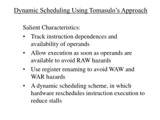
Register Renaming • Recall that the compiler generates registers to be used by the processor to compute values • Registers are often selected using a graph coloring algorithm that ensures unique data are placed in separate registers as much as possible to retain as much data in the CPU as possible • However, because of the pipeline and out of order execution hardware, the compiler’s designation of data to registers may cause conflicts • data dependencies cannot be helped, we have to live with them • name dependencies arise because of limitations on registers • An optimizing compiler may be able to rename registers to reduce the number of name dependencies that could potentially arise • Dynamic register renaming is a superior approach • This can be handled using Tomasulo’s algorithm where potential name dependencies are defeated through register renaming as the instructions are issued to their functional units
Control Dependencies • A control dependence arises due to conditional branches • Code along one branch should only be completed if the condition dictates that the branch should be taken • This means that you should not execute the if clause if the condition is false, or bypass the else clause if the condition is true, or that the loop body should be skipped if the condition is false, etc • However, with speculation, we may take or ignore branches improperly and so we have to dynamically determine if we speculated incorrectly and resolve it • Control dependencies can lead to data and name dependencies that would not normally exist • Miss-speculation can also lead to exceptions (see the next slide)
Control Dependence Problems DADD R2, R3, R4 DADD R1, R2, R3 BEQZ R2, L1 BEQZ R4, L2 LW R1, 0(R2) DSUB R1, R5, R6 L1: … … L2: OR R7, R1, R8 • The code above to the left contains a data dependence between the DADD and BEQZ but also DADD and LW • Imagine that we speculate that the branch is not taken, this would cause us to begin execution of LW • Further imagine that we do not compute the condition for numerous stages so that the LW completes first • If we have miss-speculated, then R2 == 0 and we will have attempted to load from memory location 0(R2) = 0, which is part of the OS and will most likely cause a memory violation interrupt • Thus, our miss-speculation directly caused an exception • In the code above to the right, the value of R1 changes depending on whether we took the branch or not, so a miss-speculation leads to a data hazard
Loop Unrolling Loop: L.D F0, 0(R1) ADD.D F4, F0, F2 S.D F4, 0(R1) DSUBI R1, R1, #8 BNE R1, R2, Loop Loop: L.D F0, 0(R1) DSUBI R1, R1, #8 ADD.D F4, F0, F2 stall BNE R1, R2, Loop S.D F4, 8(R1) The 2 stalls assumes no collision in the MEM stage • Compiler scheduling allows us to remove a number of stalling situations • However in concise code, there may be too few instructions to move around • Consider the code to the right • there are stalls after L.D (1), ADD.D (2), DSUBI (1) and the branch delay slot • The best we can do to schedule the code is shown to the right below, but we cannot remove all stalls • One strategy is to have the compiler “unroll” the for loop some number of iterations to provide additional instructions to schedule
Continued • We can unroll the loop 4 times • We will keep 4 iterations worth of L.D, ADD.D and S.D but only have 1 DSUBI and 1 BNE • This requires adjusting displacements for our L.D and S.D operations and the immediate datum for the DSUBI • Below to the left is the unrolled code, to the right it is scheduled, no stalls! Loop: L.D F0, 0(R1) Loop: L.D F0, 0(R1) ADD.D F4, F0, F2 L.D F6, -8(R1) S.D F4, 0(R1) L.D F10, -16(R1) L.D F0, -8(R1) L.D F14, -24(R1) ADD.D F4, F0, F2 ADD.D F4, F0, F2 S.D F4, -8(R1) ADD.D F8, F6, F2 L.D F0, -16(R1) ADD.D F12, F10, F2 ADD.D F4, F0, F2 ADD.D F16, F14, F2 S.D F4, -16(R1) S.D F4, 0(R1) L.D F0, -24(R1) S.D F8, -8(R1) ADD.D F4, F0, F2 DSUBI R1, R1, #32 S.D F4, -24(R1) S.D F12, 16(R1) DSUBI R1, R1, #32 BNE R1, R2, Loop BNE R1, R2, Loop S.D F16, 8(R1)
Complications of Loop Unrolling • Obviously we need far more registers • This is sometimes referred to as register pressure • If the loop iterates n times instead of 100, how do we know we can unroll it 4 times? • We could still unroll it 4 times and have a separate loop to iterate the final 0-3 iterations as needed • The compiler must adjust all memory displacements appropriately and the immediate datum, although this may be mathematically challenging to us, it’s a simple piece of code for the compiler • Our latencies for the example were made up to illustrate this example, imagine if we still had a 7-cycle multiply, unrolling a similar loop that performed MUL.D instead of ADD.D would be more complex – you will do this in the homework • Additionally, we must have a pipelined FP unit or else this would not be worth doing – two consecutive ADD.Ds would cause the second to stall • what would happen if we were to do DIV.D instead of ADD.D?
Dynamic Scheduling • We enhance the scoreboard concept with register renaming • This is known as the Tomasulo architecture • Our new pipeline distributes the 5 stages of MIPS differently • IF – as before, instructions are fetched and placed into an instruction queue • ID – separated into issue and read operand stages as with the scoreboard • EX – distributed pipelined functional units (e.g., FP adder, FP mult, integer), each with its own register sets (plural) to store multiple waiting instructions • MEM – a separate memory unit with a load buffer and a store buffer – instructions line up here to perform loads and stores • WB – values are forwarded directly from functional unit to functional unit, store buffer and registers via a common data bus
New Stages • Issue • Next instruction from instruction queue • Decode, check for structural hazards, if reservation station available, issue to reservation station • Read operands • Operands forwarded from Load unit, Register file or other Functional Unit to reservation station so that “read operands” when available • this means that we no longer wait on reading both operands when they are available like we did in the scoreboard • a reservation station stores operation, location operand sources and destination location • Instructions wait at reservation stations and can execute out of order based on order that operands are received • Register renaming is applied dynamically in the reservation stations to avoid WAR and WAW hazards • see the example on the next slide
Register Renaming Example DIV.D F0, F2, F4 ADD.D F6, F0, F8 S.D F6, 0(R1) SUB.D F8, F10, F14 MUL.D F6, F10, F8 DIV.D F0, F2, F4 ADD.D S, F0, F8 S.D S, 0(R1) SUB.D T, F10, F14 MUL.D F6, F10, T As long as S continues to be used for F6 and T continues to be used for F8, there is no problem with this renaming • In the code to the right • F6 causes a RAW hazard between ADD.D and S.D • nothing can be done about this • F6 causes a WAW hazard between ADD.D to MUL.D • F8 causes a WAR hazard between ADD.D to SUB.D • We rename F6 to S between the ADD.D and S.D • This does nothing to prevent the RAW hazard, but prevents the WAW hazard • We rename F8 to T between the SUB.D and MUL.D • This removes the WAR hazard with the ADD.D
Stages Continued • Execution • operands are “forwarded” to the reservation station • once operands are available (must wait for any RAW hazards), execution can begin in the functional unit • if multiple instructions’ operands become available at the same time, they can all begin execution simultaneously as long as they are at different functional units • if two instructions of the same functional unit become available at the same time, the instruction to begin is selected randomly (except for loads/stores which are handled in order) • Any instruction that is control dependent is not allowed to execute until the branch condition has been confirmed • this may slow down processing but it ensures that miss-speculation cannot cause an exception • Write result • Once a value has been computed, it is forwarded via CDB to waiting reservation stations, store buffer and register file • however if multiple functional units complete at the same time, forwarding has to be done in sequential order
How Register Renaming Works • We need to implement register renaming in hardware • A register renamer (hardware) is added to the issue stage • It maintains a list of temporary registers, called T registers • It maintains a rename table • When the renamer sees a destination register that causes a WAW or WAR conflict • It substitutes the destination register with the next available T register and adds the old and new registers to the register table • Now, for every new instruction’s source register that matches an entry in the table, replace it with the T register • The architecture might have as many as 64 T registers which are rotated (when a register is no longer in use, it becomes available to be reused) • This requires examining the table each cycle • the table is in reality a simple hardware-stored vector that can accommodate an access per clock cycle
Example Loop: L.D F4, 0(Rx) MUL.D F2, F0, F4 DIV.D F8, F4, F2 L.D F4, 0(Ry) ADD.D F6, F0, F4 SUB.D F8, F8, F6 S.D F8, 0(Ry) In the first iteration becomes: Loop: L.D T9, 0(Rx) MUL.D T10, F0, T9 DIV.D T11, T9, T10 L.D T12, 0(Ry) ADD.D T13, F0, T12 SUB.D T14, T11, T13 S.D T14, 0(Ry) • Consider the code to the right • Assume that the loop will be unrolled in a Tomasulo-type architecture • How will register renaming operate assuming that the next available T register is T9? Each successive iteration of the loop will continue To use additional T registers, the next iteration Will use T15-T20, followed by T21-T26, etc If we reach T63, we cycle around to T0
Example L.D F6, 32(R2) L.D F2, 44(R3) MUL.D F0, F2, F4 SUB.D F8, F2, F6 DIV.D F10, F0, F6 ADD.D F6, F8, F2 They have changed the execution times of all FP operations to be 4 cycles so that FP – FP delays are 3 cycles and FP – store delays are 2 cycles
Continued Register renaming is handled through forwarding from the functional unit(s) responsible for delivering the operands, this is denoted through the Qj/Qk fields above and the register status below
Dynamic Loop Unrolling • The Tomasulo architecture improves over the Scoreboard because instructions can complete without having to wait on WAW and WAR hazards • However, the real power behind the approach is the dynamic issuing of instructions • This allows instructions to be sent to reservation stations as soon as they reach the front of the instruction queue unless a functional unit’s reservation stations are all filled • Rather than using a compiler to unroll and schedule a loop, the hardware can execute many iterations of a loop without waiting for one iteration to complete • Recall in the pipeline, one iteration would stall the pipeline waiting for completion because of the lengthy computation times for FP operations • The only disadvantage of the dynamic approach is that we are not removing branch operations as we did with the compiler, however, with proper branch speculation, we can minimize the branches’ impacts on performance
Continued • With dynamic loop unrolling, we have to worry about an excessive number of WAR and WAW hazards arising by the use of the same registers across loop iterations • Previously, the compiler took care of register renaming for us by altering the registers used in each iteration • Now, we have to rely on the register renamer and the T registers • How many iterations can we unroll? In part, it will be restricted by the number of T registers available • in our previous example, we used 6 T registers per iteration and had 64 T registers, so at most, we could only accommodate 10 unrolled loops at any one time • this seems more than reasonable because there shouldn’t be that iterations that need to be unrolled to account for any FP latencies, but recall that our loop performed DIV.D • if we have a divider that takes more than 10 cycles to execute, we could easily run out of registers
Example Here is the similar loop to the one we unrolled by compiler The MUL.D’s latency causes stalls that cannot be removed through instruction scheduling because there are not enough instructions available Loop unrolling and scheduling resolved all stalls, however loop unrolling is not without its own problems (compiler complexity, need for many more registers, problems if the number of loop iterations is not divisible by the number of times we unrolled the loop (4 in the example)
Summary on Tomasulo • Notice in the previous example that we unrolled the loop two times and the hardware was able to execute the two iterations with only RAW hazards as delays • However, given the limitation on FUs, we were not able to unroll the loop further • with fully pipelined functional units, or multiple functional units, and numerous reservation stations, we could continue to execute iterations of the loop without delay • Additionally, if memory accesses cause a stall because of a cache miss, the hardware is able to continue issuing instructions out of order, thus greatly improving performance over shutting down the pipeline because of the cache miss • Also, compiler optimizations are no longer essential to obtain performance increases
Continued • The bottleneck for Tomasulois primarily the single CDB • We can improve on this by having two, one for FP and one for INT values • We also see impacts because of • The limited number of FUs • The limited number of reservation stations • Restrictions on single data accesses (loads/stores) per cycle • The added cost because of additional logic to look for potential WAR/WAW hazards and perform register renaming • However, the dynamic issuing allowed by the Tomasulo approach will encourage the use of speculation to keep the hardware busy • This will also lead to an easier way to perform superscalar pipelining (we will cover this idea next week)