Download
1 / 26
270 likes | 463 Vues
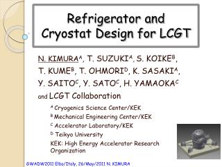
Refrigerator and Cryostat Design for LCGT. N. KIMURA A , T. SUZUKI A , S. KOIKE B , T. KUME B , T. OHMORI D , K. SASAKI A , Y. SAITO C , Y. SATO C , H. YAMAOKA C and LCGT Collaboration. A Cryogenics Science Center/KEK B Mechanical Engineering Center/KEK C Accelerator Laboratory/KEK

E N D
Refrigerator andCryostat Design for LCGT N. KIMURAA, T. SUZUKIA,S. KOIKEB, T. KUMEB, T. OHMORID, K. SASAKIA, Y. SAITOC, Y. SATOC, H. YAMAOKAC and LCGT Collaboration A Cryogenics Science Center/KEK B Mechanical Engineering Center/KEK C Accelerator Laboratory/KEK D Teikyo University KEK: High Energy Accelerator Research Organization
Outline • LCGT cryogenics • Cooling option for the Mirror • Thermal Analysis • Mechanical Analysis • Materials (New MLI for LCGT) • Summary
Structure of Mirror Cryostat Cryostat with four cryocooler units to SAS Cryostat Stainless steel t20mm Diameter 2.4m Height ~3.8m M ~ 10 ton Drawn by S. Koike (KEK) Remote valve View ports ~3.8m Low vibration cryocooler unit Main LASER beam Cryocoolers Pulse tube, 60Hz 0.9 W at 4K (2nd) 36 W at 50K (1st) Main beam (1200mm FL) 2.4m
Basic requirements from the LCGT cryogenics ISSUES • Temperature of the test mass/mirror : 20 [K] • Inner radiation shield have to be cooled to < 8 K • Cool the mirror without introducing excess noise, • especially vibration due to cryo-coolers. • Easy access and enough space • for installation work around the mirror. • Satisfy ultra high vacuum specification < 10-7 Pa Estimated by Dr. Uchiyama (ICRR) I was requested make a design for the LCGT cryostat from ICRR just One year ago!
Cooling Option Our decision: Use CLIO type Cryo-coolerwith low vibration mount for LCGT Heat Link Vibration Reduction Stage Cold Stage VRS
Advantage and Disadvantage of CLIO type cryocooler unit Disappeared Items • Ready to use Cryo-Cooler equipped special cold stage, such as CLIO type • Aluminum FRP tube as anti-vibration support rods • High pure aluminum thin wire less than f0.12 mm • for heat link. • Substitutes for the Items • Attach new design of cold stage flanges • to mass-produced 1W/4K PTC • Replace to Carbon FRP tube as anti-vibration support rods (stiffness AFRP > CFRP > GFRP) • Start R&D work with new company • for development of high pure aluminum thin wire less than f0.12 mm. Advantage • Basic concept of design has been established since the R&D done in CLIO. (2001~2003) Disadvantage • Some critical components are unavailable today. Reasons are in the followings. • Withdrawal business by social condition • A change of generation of experienced workers • Replace or renewal of the equipment of a factory We have to find substitutes!
Other Candidate => re-condensation cryo-cooler • Example; SCGR meter, g-2 project at J-PARC • The g-2 SC magnet is required with very high magnetic field uniformity below the level of 0.1 ppm. • Field quality is sensitive to relative position btw yoke and coil • random & individual vibration due to mechanical resonance • -> disturb uniform field It needed more R&D worker than to find substitutes materials for the new CLIO type cryo-cooler, when the project was started.
An Estimated Break Down List of Thermal Budget 1st Cold stage 2nd Cold stage • Outer Shield (W) • Eleven View Ports 22 • Radiation From 300 K 70 • Support post and Rods 24 • Electrical wires 3 x 10⁻⁴ • Total 116 • W/unit 29 • Inner Shield (W) • Duct Shields* < 0.05 • (Beam and SAS) • Eleven View Ports 0.4 • Radiation From 80 K 2.2 • Support post and Rods 2.4 • Electrical wires 3 x 10⁻⁴ • Mirror Deposition 0.9 • Scattering Light ? • Total 5.9 • W/unit 1.5 *Heat Load of Duct Shields was presented by Mr. Sakakibara on Monday.
Estimated Thermal Budget Estimated Heat Loads at the radiation shields and Support posts and rods 70 W by the radiation at 80 K outer shield 2.2 W by the radiation at 8 K inner shield 2.4 W by the radiation and conduction (support posts and tension rods) at 8 K 24 W by the radiation and conduction (support posts and tension rods) at 80 K Very High Purity Aluminum Conductor (5N8) Low Vibration Cryo-cooler unit
Example of Thermal Conductivity of 6N-class Very High Pure Aluminum* 40,000 W/m/K @ 6K 6N Aluminum 5N up Al RRR=3000 For outer shield 2N Aluminum ~Type A-1070 For inner shield Cost: 5N8 > 2N Aluminum We must put the right material in the right position.
Estimated Thermal Budget Estimated Heat Loads at the radiation shields and Support posts and rods 94 K at the top of the 80 K outer shield (A1070) 7.4 K at the top of the 8 K inner shield (5N8+A1070) < 8 K at Connection point with IM 47 K at 1st cold stage of Cryo-cooler 6.5 K at 2nd cold stage of Cryo-cooler dT1st = 26 K dT2nd=0.5 K
Rough Estimation of the PTC* operationwith 20 ppm deposition by Scattering Light at 400 kW Heat load/Unit= 400 kW * 20 ppm / 4 units = 2 W/unit 5W/50W dQ=2 W 4W/40W 11 K 20 ppm deposition may be accepted, but we lost contingency cooling power of 2 W. 23 K *PTC: Pulse Tube-type Cryocooler
Doors for access to inside S. Koike Outer shield W 1600 mm X h 1900 mm W 1020 mm X h 1600 mm Inner shield
Static deformation analysis S.Koike • Main vacuum duct and the duct to SAS are not connected. • Boundary conditions • periphery of the bottom : fix
Boundary condition: fix the perimeter of the bottom Modal analysis * Interface to SAS is not fixed at the moment. S.Koike Resonance Frequency
Structure of Radiation Shields Flame by A6000 Aluminum Secure stiffness of the radiation shields Inner Shields Outer Shields
Modal analysis of outer shield S.Koike Mode frequency M= Remove support rod Mode Frequency M=
Modal analysis of inner shield S.Koike Frequency M=
Response to ground motion Jan. 31st,2011 H. Yamaoka Input to peripheral of bottom Mozumi 50m K.Y. 2005
Cryo-top Cryo-F Cryo-L Cryo-R Input Response to ground motion Y方向 X方向 X-direction Y-direction
MLI utilizes quite a lot of aluminized thin polyester films as radiation shields. • The polyester film exhausts water vapor, which may dim the optical system of the Laser-Interferometer. • The exhaust rate of the water vapor may be reduced much at cryogenic temperature. But it is important to know the general characteristics of out-gas rate at room temperature.
To reduce the total amount of out-gas, • Thickness of polyester film must be thin Light Weight MLI • Total number of films in MLI must be reduced High Thermal Resistance
Specifications of Candidate MLI : KFP-9B08 ( provided by Tochigi Kaneka Co., Ltd.) *1 : estimated by the aluminum thickness data obtained by the atomic absorption spectroscopy reported by Teikyo University in the International Conference of Cryogenic Engineering, 2010
The measurement is now underway MLI : Kaneka KFP-9B08 Back ground (SUS Chamber)
(2) High Thermal Resistance • Heat transfer mechanisms in MLI qt = qr + qc Radiation term qr and Conduction term qc are comparable at good fabrication condition. Conduction term is governed by contact pressure between reflective films at the self-compression state. Radiation term is governed by total number of films. Thin polyester film will reduce the contact pressure from thermal resistance point of view. ⇒Light weight MLI
Summary • The design of the mirror cryostat for LCGT satisfying requirements was almost finished in one year. • The production of the components for the cryostat will be started after contractor decided. • Performance of the first cryostat will be demonstrated on the mid of 2012 Jfy. • Proto type cryo-cooler units replaced with substituted materials will be completed on the end of this June. • Performance of the first cryo-cooler will be confirmed on the mid of this July.