Download

1 / 32
320 likes | 474 Vues
Design of the LCGT interferometer observation band. Masaki Ando (Department of Physics , Kyoto University). On behalf of LCGT BW special working group. Explain how the observation band of a LCGT interferometer (and the optical configuration)

E N D
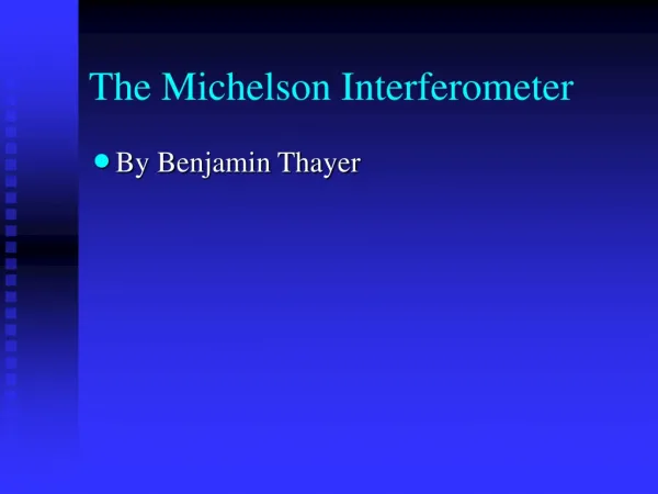
Design of the LCGT interferometer observation band Masaki Ando (Department of Physics, Kyoto University) On behalf of LCGT BW special working group GWADW2010(May 17, 2010, Kyoto, Japan)
Explain how the observation band of a LCGT interferometer (and the optical configuration) has been determined. Abstract GWADW2010(May 17, 2010, Kyoto, Japan)
Scope Interferometer observation band should be determined with investigations from various view point… Special working group Science Detection, Waveform, Astrophysical information Observation Calibration Target selection Sensitivity Stability Control scheme Schedule, Cost Project Strategy Technical Feasibility R&D GWADW2010(May 17, 2010, Kyoto, Japan)
Introduction Candidate configurations Science outcomes Technical Feasibility Project Strategy Conclusion Outline GWADW2010(May 17, 2010, Kyoto, Japan)
Introduction Candidate configurations Science outcomes Technical Feasibility Project Strategy Conclusion Outline GWADW2010(May 17, 2010, Kyoto, Japan)
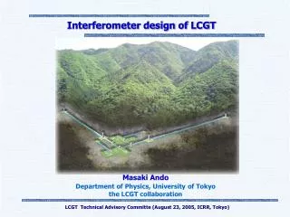
Interferometer setup LCGT baseline design Arm length of 3km, Underground site of Kamioka Cryogenic mirror and suspension High-power RSE interferometer with cryogenic mirrors Resonant-Sideband Extraction Input carrier power : 75W DC readout Main IFO mirror 20K, 30kg (Φ250mm, t150mm) Mech. Loss : 10-8 Opt. Absorption 20ppm/cm Suspension Sapphire fiber 16K Mech. Loss : 2x10⁻⁸ GWADW2010(May 17, 2010, Kyoto, Japan)
RSE and cryogenics RSE High arm-cavity finesse moderate Power recycling gain Smaller optical loss and absorption in ITM substrate Figure: K.Somiya high power and cryogenics GWADW2010(May 17, 2010, Kyoto, Japan)
Quantum and Classical noises Quantum noise is dominant Optimization of RSE configuration Tuning of obs. band DC readout Rooms for improvement Figure: K.Somiya GWADW2010(May 17, 2010, Kyoto, Japan)
Introduction Candidate configurations Science outcomes Technical Feasibility Project Strategy Conclusion Outline GWADW2010(May 17, 2010, Kyoto, Japan)
Tuning of observation band Tune the resonance condition of Signal-Extraction Cavity Enhance IFO response, Reduce quantum noise at certain frequency band Optimal reflectivity of mirrors are different in Broadband RSE (BRSE) and Detuned RSE (DRSE) configurations SEC Variable RSE (VRSE) Change tuning without replacement of mirrors or changing in macroscopic position Figure: K.Somiya GWADW2010(May 17, 2010, Kyoto, Japan)
Candidate configurations 4 candidate configurations Broadband Detuned FixedBRSEDRSE VariableVRSE-BVRSE-D Optimize parameters for Neutron-star binary inspirals (Primary target of LCGT) Arm cavity finesse, SEC finesse Detuning phase, DC readout phase Figure: K.Somiya GWADW2010(May 17, 2010, Kyoto, Japan)
Introduction Candidate configurations Science outcomes Technical Feasibility Project Strategy Conclusion Outline GWADW2010(May 17, 2010, Kyoto, Japan)
Observable range Detection rate BRSE 114 Mpc 5.4 yr-1 VRSE-B 112 Mpc 5.2 yr-1 VRSE-D 123 Mpc 6.9 yr-1 DRSE 132 Mpc 8.2 yr-1 (SNR 8, Sky averaged) Neutron-star binaries Primary purpose of LCGT: Detection of GW First target : Neutron-star binary inspirals Observable range : estimated from sensitivity curve Event rate : V. Kalogera et.al., ApJ, 601 L179 (2004) Galaxy number density : R. K. Kopparapu et.al., ApJ. 675 1459 (2008) GWADW2010(May 17, 2010, Kyoto, Japan)
IR DP BRSE 114 Mpc VRSE-B 112 Mpc VRSE-D 123 Mpc DRSE 132 Mpc Detection probability Detection probability in one-year observation 99.6 % 99.4 % 99.9 % 99.9 % Success probability of the LCGT project Assume Poisson distribution Figure: N.Kanda GWADW2010(May 17, 2010, Kyoto, Japan)
Parameter Estimation Errors in parameter estimation from observed waveform SNR Arrival time Mass parameters By H.Tagoshi DRSE has better observable range, but poorer astrophysical information (factor ~2 difference) GWADW2010(May 17, 2010, Kyoto, Japan)
Binary black hole Obs. range : 570-670 Mpc Black hole Quasi-Normal mode Obs. range : 2-3 Gpc Core-collapse supernova Galactic events are detectable Out of band for DRSE ? Other Targets Pulsars 25-38 pulsars within band Better sensitivity than spin-down upper limit Less targets for DRSE BRSE DRSE Figure: Y.Miyamoto GWADW2010(May 17, 2010, Kyoto, Japan)
Introduction Candidate configurations Science outcomes Technical Feasibility Project Strategy Conclusion Outline GWADW2010(May 17, 2010, Kyoto, Japan)
Mainly discuss the difference in technical difficulties though there will be many common problems… Technical feasibility ・IFO Control (Signal extraction and SNR, Coupling noise by control) No critical difference, though each configuration has advantages and disadvantages VRSE : realized by additional offset to the error signal ・Requirement for mirror High arm-cavity finesse (1550) in BRSE, VRSE lower optical loss is required (45ppm) Backup plan: Increase of input power, tuning of opt. Config. No critical difference GWADW2010(May 17, 2010, Kyoto, Japan)
Control scheme 5 length DoF should be controlled in RSE Figure: K.Somiya Signals are extracted with RF sidebands at two freq. GWADW2010(May 17, 2010, Kyoto, Japan)
SEM control and VRSE VRSE is realized by adding an offset in SEM control signal DRSE Tradeoff between signal strength and control range Signal strength depends on the finesse of SRC + SEC VRSE BRSE Figure: K.Somiya GWADW2010(May 17, 2010, Kyoto, Japan)
Control loop noise Figure: K.Somiya GWADW2010(May 17, 2010, Kyoto, Japan)
Control loop noise Control loop noise in VRSE Normal operation with VRSE-B, control offset for VRSE-D VRSE-B VRSE-D Figure: O. Miyakawa Contribution of l- and ls loop noise does not degrade the sensitivity. GWADW2010(May 17, 2010, Kyoto, Japan)
Introduction Candidate configurations Science outcomes Technical Feasibility Project Strategy Conclusion Outline GWADW2010(May 17, 2010, Kyoto, Japan)
LCGT should contribute to the first detection Earlier start of observation is desirable Should consider the total time of Commissioning termand Observation time required for the first detection. ・Observation time for the first detection Two month difference at most ・Commissioning term Many uncertainties Difficult to predict in precision of month In the best guess from current experiences… No critical difference. ・Cost, Risks, Room for future upgrades No critical difference. Project Strategy GWADW2010(May 17, 2010, Kyoto, Japan)
Introduction Candidate configurations Science outcomes Technical Feasibility Project Strategy Conclusion Outline GWADW2010(May 17, 2010, Kyoto, Japan)
Summary We compared 4 candidate configurations Broadband RSE (BRSE), Detuned RSE (DRSE), Variable RSE (VRSE-B, VRSE-D) Science Detection, Waveform, Astrophysical information Observation Calibration Target selection Sensitivity Stability Control scheme Schedule, Cost Project Strategy Technical Feasibility R&D GWADW2010(May 17, 2010, Kyoto, Japan)
1. LCGT should be Variable RSEconfiguration(VRSE). 2.In the first stage, it should be at the detuned operation point(VRSE-D). In 4 candidate configurations, … ・No critical difference in detection probabilities. ・No critical difference in technical feasibilities. ・DRSE is tuned for detection of BNS event, but has less capabilities for the other targets. ・ VRSE-Dis slightly better sensitivity for BNSthan VRSE-B. ・We have an option to be VRSE-B after first few detections, for wider scientific outcomes. Conclusion GWADW2010(May 17, 2010, Kyoto, Japan)
Conclusion Summary of LCGT interferometer parameters By K.Somiya GWADW2010(May 17, 2010, Kyoto, Japan)
Acknowledgements Special Working Group members Coordinator: Seiji Kawamura (NAOJ) Chair: Masaki Ando (Kyoto University) Members: Nobuyuki Kanda (Osaka City University), Yoichi Aso (University of Tokyo), Kentaro Somiya (Caltech), Osamu Miyakawa (ICRR), Hideyuki Tagoshi (Osaka University), Daisuke Tatsumi (NAOJ), Hirotaka Takahashi (Nagaoka University of Technology), Kazuhiro Hayama (AEI), Kazuhiro Agatsuma (NAOJ), Koji Arai (Caltech), Kiwamu Izumi (NAOJ), Yuji Miyamoto (Osaka City University), Shinji Miyoki (ICRR), Shigenori Moriwaki (University of Tokyo), Shigeo Nagano (NICT), Noriaki Ohmae (University of Tokyo), Shuichi Sato (Hosei University), Toshikazu Suzuki (KEK), Ryutaro Takahashi (NAOJ), Takashi Uchiyama (ICRR), Hiroaki Yamamoto (Caltech), Kazuhiro Yamamoto (AEI) Special thanks to the external evaluation committee : Stan Whitcomb (Chair), Stefan Ballmer, Hartmut Grote, Benoit Mours, Peter Shawhan GWADW2010(May 17, 2010, Kyoto, Japan)
End GWADW2010(May 17, 2010, Kyoto, Japan)
BRSEVRSE-BVRSE-DDRSE Scientific outcomes GWADW2010(May 17, 2010, Kyoto, Japan)
Scope: To make recommendations on the interferometer optical configuration design of LCGT, and its observation band for gravitational waves. Members: 22 members from LCGT collaborators Reviewed by an external evaluation committee LCGT BW special working group GWADW2010(May 17, 2010, Kyoto, Japan)