Download
1 / 43
430 likes | 565 Vues
CURRENT SKA TDP ANTENNA DESIGN 10. DVA1 Meeting at NSF Arlington VA April 15-16, 2010 Matt Fleming. Contributions from Jack Welch Roger Schultz Gordon Lacy. Antenna Design Drivers. Must achieve survival. ( 100 mph wind )

E N D
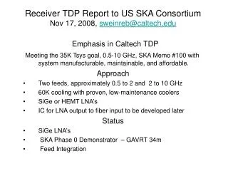
CURRENT SKA TDP ANTENNA DESIGN 10 DVA1 Meeting at NSF Arlington VA April 15-16, 2010 Matt Fleming Contributions from Jack Welch Roger Schultz Gordon Lacy
Antenna Design Drivers • Must achieve survival. • ( 100 mph wind ) • 2 Low cost per unit area of aperture. ( good sky coverage ) ( installed ) • ( low cost materials, low mass design, low fabrication labor ) ( favors symmetric ) • 3 Very low operational cost for a 30 year life • ( very few maintenance visits required ) • 4 Frequency range of 0.3 to 10 GHz with WBSPF • ( 3.5m Gregorian secondary ) ( favors offset ) • 5 Excellent Ae / Tsys. • ( accurate surfaces, controlled spillover, low diffraction ) ( favors offset ) • 6 Exceptional dynamic range. • ( very rigid surfaces, very good pointing, ) pt source sensitivity survey survey speed Performance vs Cost Tradeoffs These will lead to specifications: ??? DVA1, NSF, Arlington, 2010-04-16 Matt Fleming slide 2 of 43
Basic fabrication cost drivers • Raw material costs. ( fairly constant world wide )( a good design is light weight ) • Labor cost. ( varies by type and location based on economic and social conditions ) Technology. ( application of intellect to use of material, labor & energy ) Number of units needed. ( investment in tooling ) Transportation. ( where made, where assembled, where installed ) For some designs material is often traded for labor Understanding these items for every design allows engineering shortcuts We cannot do detailed design on every possible design approach DVA1, NSF, Arlington, 2010-04-16 Matt Fleming slide 3 of 43
Note on Transportation Physical size of antenna elements will influence transport cost. Remote fabrication of smaller elements allows use of global labor competition. Remote fabrication usually means greater on site assembly labor. Onsite fabrication of large elements can allow lower on site assembly labor. Non modal transport is also possible, but likely more expensive. DVA1, NSF, Arlington, 2010-04-16 Matt Fleming slide 4 of 43
This slide just a reminder about initial choices Types of Reflectors & Support This is an arbitrary identification system just for discussion DVA1, NSF, Arlington, 2010-04-16 Matt Fleming slide 5 of 43
Single shell or stressed skin • Single piece reflectors often have low labor cost relative to alternate designs. • Reflector edge support by itself preserves accuracy extremely well. • The reflector surface can act as the structural front side of a deeper system. • Rim edge and center support works better if the center has axial flexibility. • The concept can work for symmetric or offset designs. Primary as a monocoque element Jump to single shell On Az-El mount DVA1, NSF, Arlington, 2010-04-16 Matt Fleming slide 6 of 43
ATA Implementation • A frame & spar system gives good edge & center support with an open center. • Wind & gravity moment loads are reduce with Az & El near the shell center. • The support system allows a compact turret head to be nested close to shell. • A compact turret head can contain almost all the precision machining needs. • A relatively simple pipe pedestal can support the turret head. ( wind & thermal ) DVA1, NSF, Arlington, 2010-04-16 Matt Fleming slide 7 of 43
JPL, DSN, Prototype • A 6.1m diameter symmetric shell can be made with only a 3mm thickness. • The surface accuracy can be quite high. • A study showed 3mm alum 3003 will have good repeatability in production . • Another study showed 3mm alum 3003 can be extended to a 12m symmetric. DVA1, NSF, Arlington, 2010-04-16 Matt Fleming slide 8 of 43
Identify 3 Optical Designs of Interest Data points for SKA cost model Inform Tradeoff symmetric vs offset D1 E1 B1 E2 DVA1, NSF, Arlington, 2010-04-16 Matt Fleming slide 9 of 43
Select 3 Designs for Costing FEA Design & Costing for HMR to meet survival requirements HMR = Hydroformed Metal Reflector DVA1, NSF, Arlington, 2010-04-16 Matt Fleming slide 10 of 43
Canada DRAO CART Project and South Africa MeerKAT Project have generated cost and performance information for composite on site reflector fabrication. Information from Composite Investigations Prototype 10m complete. Symmetric with Core, Beams & Hub. SKA Memo 116 costing information Starting to investigate Offset monocoque V3 DRAO = Dominion Radio Observatory CART = Composite Application Radio Telescope DVA1, NSF, Arlington, 2010-04-16 Matt Fleming slide 11 of 43
( survival design shown )( add 15% for performance design ) TDP Antenna Cost ( summary estimates ) 0% 8% 15% 0% 11% 25% Adding 15% 113,000 122,000 130,000 137,000 152,000 Preliminary DVA1, NSF, Arlington, 2010-04-16 Matt Fleming slide 12 of 43
TDP Antenna Cost (summary estimate )a little more detail Masses are low Preliminary DVA1, NSF, Arlington, 2010-04-16 Matt Fleming slide 13 of 43
Preffered mechanical configuration Acceptable optical configuration Costing Allows Selection Optics 42 used for costing 2 Gregorian feeds with rotary indexer & possibly a PAF Shown with Feed Up but optics can be the same with Feed Down PAF = Phased Array Feed Note feed support locations DVA1, NSF, Arlington, 2010-04-16 Matt Fleming slide 14 of 43
HMR monocoque appears to perform well Computed RMS 0.008 inches 0.20 mm Preliminary DVA1, NSF, Arlington, 2010-04-16 Matt Fleming slide 15 of 43
Computed RMS 0.013 inches 0.33 mm Preliminary DVA1, NSF, Arlington, 2010-04-16 Matt Fleming slide 16 of 43
Computed RMS 0.001 inches 0.03 mm Preliminary DVA1, NSF, Arlington, 2010-04-16 Matt Fleming slide 17 of 43
Both hydroformed metal and fiber reinforced plastic create good monocoque structures HM & FRP shells are similar FRP can replace HM reflectors and can provide edge support DVA1, NSF, Arlington, 2010-04-16 Matt Fleming slide 18 of 43
Preliminary Specifications 1 of 2 DVA1, NSF, Arlington, 2010-04-16 Matt Fleming slide 19 of 43
Preliminary Specifications 2 of 2 DVA1, NSF, Arlington, 2010-04-16 Matt Fleming slide 20 of 43
Beginning to work on details Survival wind Rain snow ice Security and vandalism Ease of maintenance DVA1, NSF, Arlington, 2010-04-16 Matt Fleming slide 21 of 43
Additional Views DVA1, NSF, Arlington, 2010-04-16 Matt Fleming slide 22 of 43
Structural Simplicity More about PAF position later Triangular deep trusses good Cured beams and curved shells bad Tubular structures are very efficient at handling bending and torsion DVA1, NSF, Arlington, 2010-04-16 Matt Fleming slide 23 of 43
Pedestal Mount & Frame DVA1, NSF, Arlington, 2010-04-16 Matt Fleming slide 24 of 43
Deliverable Antenna Elements Secondary Primary not shown It is an on site fabrication Feed and indexer Primary center frame Secondary and feed support Electronics enclosures Pedestal Turret head DVA1, NSF, Arlington, 2010-04-16 Matt Fleming slide 25 of 43
Pedestal Fabrication Machined Flange Consider use of ring forgings Alternate foundation concepts are still under consideration DVA1, NSF, Arlington, 2010-04-16 Matt Fleming slide 26 of 43
Transport Check Looks good for global sourcing DVA1, NSF, Arlington, 2010-04-16 Matt Fleming slide 27 of 43
Turret Head Assembly Deliverable Assembly Includes az drives, bearings, encoders, electronics DVA1, NSF, Arlington, 2010-04-16 Matt Fleming slide 28 of 43
Transport Check Looks like a little larger is possible. Note 3.1 m secondary shown DVA1, NSF, Arlington, 2010-04-16 Matt Fleming slide 29 of 43
Primary Center Frame Pentagonal frame shown Tubes all have parallel end cuts Machining of this portion may be necessary and a little expensive DVA1, NSF, Arlington, 2010-04-16 Matt Fleming slide 30 of 43
Not so good Transport Check Design for assembly or ship prepared kit to near site fabricator for final weld and paint then transport to site. DVA1, NSF, Arlington, 2010-04-16 Matt Fleming slide 31 of 43
Secondary Support Frame More information is needed about feed support requirements. If made from metal, we will consider some on site assembly. FRP fabrication may be ideal for rear section from the primary lower rim to the feed support plane. DVA1, NSF, Arlington, 2010-04-16 Matt Fleming slide 32 of 43
Not good Density very poor Reconsider this Transport Check Design for assembly or ship prepared kit to near site fabricator for final weld and paint then transport to site. Electronics enclosure shown DVA1, NSF, Arlington, 2010-04-16 Matt Fleming slide 33 of 43
Turret Head & Az drives Deliverable Assy Machined fabrication Double row ang contact Or crossed roller With oil bath Az drive modules Lubrication 60 months DVA1, NSF, Arlington, 2010-04-16 Matt Fleming slide 34 of 43
Azimuth Drives Dual idler supported pinion Multiple modular drives Access to drives RFI control Full oil bath lubrication for 60 month period DVA1, NSF, Arlington, 2010-04-16 Matt Fleming slide 35 of 43
Currently envision a custom actuator El Bearings & El drive Gravity loading helpful. Low clearance important Bearing choices tuff. DVA1, NSF, Arlington, 2010-04-16 Matt Fleming slide 36 of 43
Encoders & Pointing Both encoders can be interior to the turret head allowing environmental protection and easy cabling. Unatainium box on back of dish is the best option Long light weight tube might be problematic Limit switch gearing Addition of tilt meter and accelerometer devices may enhance performance Attachment to reflector surface away from loaded areas Az tube could extend to ground for higher accuracy, but ……. DVA1, NSF, Arlington, 2010-04-16 Matt Fleming slide 37 of 43
Cable Wraps & Enclosures Current Az wrap 540° and envisioned with only 5 elements Power 1, Power 2, Ground, Control fibers, Signal fibers Current El wrap 75° envisioned with many elements Power 1, Power 2, Ground, Control fibers, Signal fibers Security, access, swapping Cooling is important to consider early in the design DVA1, NSF, Arlington, 2010-04-16 Matt Fleming slide 38 of 43
ATA in glass Lindgren in can PAF shown 1m x 1m x 1m Feeds and Indexer 1 Track ? Pivot & structural support Maybe sector not turntable Min angle on wraps PAF at secondary focus still under consideration Space for PAF implies two leg support frame DVA1, NSF, Arlington, 2010-04-16 Matt Fleming slide 39 of 43
Feeds and Indexer 2 Some comments: It will be expensive. It will introduce additional deflection. It will introduce additional pointing considerations. It will require more cables and cable wrap loading. Is it really possible to imagine future feed upgrades? I look at the ATA WBSPF with 1.0 to 10.0 GHz, weighing 40 Kg and wonder If we gave 0.3 to 1.0 GHz to another solution then the dish is much simpler. DVA1, NSF, Arlington, 2010-04-16 Matt Fleming slide 40 of 43
Mount Discussions DVA1, NSF, Arlington, 2010-04-16 Matt Fleming slide 41 of 43
Issues to rememberand questions remaining For the DVA-1 Diameter Primary ( 12 15m )( done ) Diameter Secondary ? ( 4m ) go to ( 3.5 ) Optics design – shaping – illumination angle ? High shrouding concept. Analysis high shroud ? High Low decision ? Diffraction from secondary support braces and other items ? Tolerances on component positions ? Determine spec for high performance US SKA Consortium, Madison, 2008-11-17 Matt Fleming slide 42 of 35
Questions DVA1, NSF, Arlington, 2010-04-16 Matt Fleming slide 43 of 43