ANTENNA DESIGN
ANTENNA DESIGN. Texas Instruments TRF 6900. Overview. The Normal Mode Helical Antenna was selected, primarily for its small profile and relative ease of construction. A prototype was constructed based on published formulas The prototype was found to have several deficiencies in performance.


ANTENNA DESIGN
E N D
Presentation Transcript
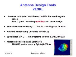
ANTENNA DESIGN Texas Instruments TRF 6900
Overview • The Normal Mode Helical Antenna was selected, primarily for its small profile and relative ease of construction. • A prototype was constructed based on published formulas • The prototype was found to have several deficiencies in performance
Antenna Design Scheme • Initial antenna design and evaluation • Optimize characteristics by varying antenna dimensions and configuration • Perform preliminary tests with network analyzer to determine effects of changes • Implement desirable modifications and perform radiation pattern and gain tests
Experimental Modifications • Increased ground plane area • Increased pitch angle • Varied helix diameter • Varied number of helix turns • Installed stub between helix and ground plane
Task Detail • Prototype Antenna: Research, build and test - James Furse, Aden Wilson • Vary antenna dimensions and observe changes- James Furse, Aden Wilson • Implement and test beneficial modifications in design - James Furse, Aden Wilson • Develop Matlab program to plot radiation patterns from data – James Furse • Implement and test centrally located stub - James Furse, Aden Wilson • Develop and implement Impedance matching network - Farhan Khan • Test antennae with PC-PC link - James Furse, Aden Wilson, Farhan Khan (tentative) • Develop and implement antenna enclosure/support- James Furse, Aden Wilson (tentative)
Timeline (Tasks completed) • 09/14 Research antenna designs • 10/02 Select antenna type • 10/05 Calculate preliminary dimensions • 10/08 Build prototype antenna • 10/10 Perform testing of prototype • 10/12 Alter various dimensions to optimize characteristics • 10/12 Implement changes in a series of test antennas • 10/12 Test effects of changes • 10/13 Implement beneficial changes to optimize design • 10/25 Build final design • 10/25 Begin research of impedance matching methods • 10/26 Test final design
Timeline (Tasks incomplete) • 11/05 Build impedance matching circuit (if needed) • 11/05 Implement impedance matching circuit (if needed) • 11/12 Test antenna on PC-PC link • 11/12 Modify design (as needed) • 11/19 Design and implement antenna enclosure • 11/19 Design complete
Why do we need an Impedance Matching Circuit? • USB Board is configured to 50Ω, while the Antenna is receiving at approximately 40Ω. • Impedance mismatch will cause distortion and reflection back from the intended load.
Transformer Circuit Advantage The connection effects an improvement in the amount of power transferable between different impedance levels. Disadvantage The circuit can be quite complex, and the theoretically calculated transformer values may require extensive tuning.
Advantages The least complex impedance matching circuit Requires less tuning Disadvantages Suits either High Pass or Low Pass, but not both Component values can be limited Lumped Component Circuit
Antenna Characteristics • VSWR (Voltage Standing-Wave Ratio) = 1.375 • @ 915MHz • Always High Pass Bandwidth of 30 MHz The Choice Lumped Component Circuit