The Layers of a Network and Error Correction
230 likes | 497 Vues
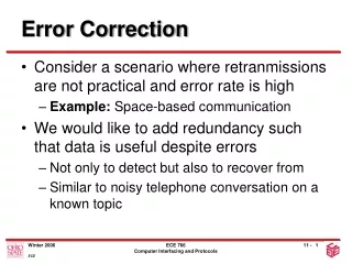
The Layers of a Network and Error Correction. Wade Trappe. Lecture Overview. Layers Components The 7 Layers of OSI Their Purpose Error Correcting Codes Definitions Some Basic Results Major Math will be presented on the board. Layering.

The Layers of a Network and Error Correction
E N D
Presentation Transcript
The Layers of a Networkand Error Correction Wade Trappe
Lecture Overview • Layers • Components • The 7 Layers of OSI • Their Purpose • Error Correcting Codes • Definitions • Some Basic Results • Major Math will be presented on the board
Layering • The idea of layering is fundamental to network design • Although Protocol Layering is covered in detail in Communication Networks II, it useful to have some awareness of layering for this class as the basis for discussion • Tasks can be broken down into individual subtasks– a network involves many subtasks, or services, some of which are independent of each other, some dependent • The most common form of dependency is where Protocol A uses Protocol B in its execution • Example: File Exchange, one protocol is the file exchange, another is involved in transferring a smaller data unit (packet) from the sender to receiver • This transfer is called a data transfer, and is part of a data transfer protocol
Layering, pg. 2 • This type of dependency is fundamental, it leads to the idea of layering (e.g. the file transfer is a layer above the data transfer) • The interface between a lower layer and an upper layer is called a service access point (SAP) • The packets or messages exchanged between entitites in the same layer are protocol data units (PDUs) • Packets handed by upper layers to lower layers are service data units (SDUs) • PDUs are basically SDUs are SDUs with extra header info. Upper Layer PDUs SDUs SAP PDUs Lower Layer
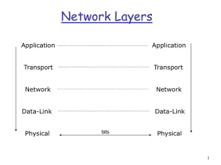
Layering, pg. 3 • Layering provides abstraction, hiding the issues of one layer from another • This is good engineering: • It means you don’t have to worry about all the unnecessary details above or below your layers • It is bad as information is hidden from you that might be useful and might affect performance • Additional advantage is that layering facilitates standardization • The Open System Interconnect (OSI) reference model developed by the International Organization for Standards (ISO) is the basic generic reference model used to discuss network protocols • OSI is not used in practice
Seven OSI Layers Sender Receiver Application Application Presentation Presentation Session Session Intermediary Transport Transport Network Network Network Datalink Datalink Datalink Physical Physical Physical Physical Medium
Tour De’Layers • Physical Layer: • Provides the ability to transmit a sequence of bits between any two nodes joined by a physical communication channel. • The physical interface module is called a modem • Datalink Control Layer: • Each point-to-point communication link (aka a bit pipe provided by Layer 1) has data link control modules at each end of the link • The objective of the DLC is to convert unreliable bit pipe into a virtual link for sending error-free packets over the link • Asynchrony involved: • Delay (variable) from correcting errors and packet size • Packets from higher layers might arrive at variable times • DLC is accomplished by: adding header and trailer bits around a packet to form a larger stream called a frame • Purpose of these bits is error correction, retransmission, and start/stop marking • In many networks, we have a multiple access channel (shared medium). Tasks of administering and resolving conflicts are relegated to the MAC sublayer (medium access control).
Tour De’Layers, pg. 2 • Network Layer: • Each node on the network uses its Network Layer Process to determine how to send information between two network entities • To do this, it uses the packet header information plus locally stored information to perform routing and flow control • Routing: Determines the path that the message will take through the intermediate nodes before getting to the end host • Flow/Congestion Control: The goal is to adjust the rate of flow of packets into the network in order to control congestion along the entire path • Transport Layer: • Breaks messages into smaller data units “packets” at the transmitting end and reassembles them at the receiving end • Key issues of buffer management arise (buffer memory, packet reordering etc) • Multiplex many separate low-rate sessions into a single higher rate session to be handed to the network layer (reduces overhead) • Split higher-rate session into several lower rate sessions (for flow control) • Reliability
Tour De’Layers, pg. 3 • Session Layer: • Provides service look up • Provides access control (restrict communication between two entities based on the network information) • Controls interaction between two endpoints • Presentation Layer: • Data encryption • Data compression • Code Conversion (variations of ASCII) • Application Layer • Software needed to perform operations/services • Often application and presentation are bundled together
Physical Layer Media • There are many different types of media over which networks are built. The main three are • Transmission Lines • Fiber Optics • Microwave Radio • For each type of media, the most common form of communication involves the use of a carrier wave • This means that our information rides “on top” of a narrowband signal • The purpose of the carrier wave is to place information at a particular frequency range where it will not interfere (or coexist) with too many other types of signals • The information has a finite bandwidth and is conveyed around a center frequency known as the carrier: • If s(t) is a signal with baseband information/spectrum, then s(t)eiw0t
A Little More PHY (but not much!) • Information is encoded into waveforms through modulation– this is covered in Digital Communications classes. • The communications channel is the source of distortions that are introduced. • The corresponds to the transmission medium and, in general, poses constraints as well as introduces distortions • Bandwidth constraint: The limitations on the amount of bandwidth that may be conveyed by the medium (incorporates issues such as the spectral shape of the medium) • Transmitted Power Constraint: Limitations on the amount of power used in transmission– perhaps to limit cross-channel interference, or because of non-linear “threshold” effects of the medium (saturation) • The types of distortion that the medium introduces are: • Attenuation • Delay • Limited Bandwidth • Line/Channel Noise
A Little More PHY (but not much!), pg. 2 • Break to draw a couple diagrams and some explanations on the chalk board • Discuss each type of distortion
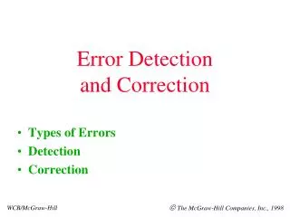
After PHY Comes • The result of the physical layer is an unreliable bit pipe (a stream of bits) • We now move up one layer to the Data Link Control Layer • There are several key issues that are handled by the DLC: • Framing: How to decide where to start and stop “packets” given the stream of bits coming out of the bit pipe • Error Detection/Correction • Retransmissions • Handle issues associated with multiple access • We begin with error detection and correction, and assume (for now) that the big issue of framing has been solved • Our question is: How to determine if a frame/packet has an error?
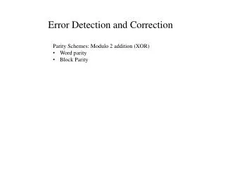
Simple Error Correction • The simplest form of error detection is through parity checks • A single parity check involves taking a string of bits of fixed length and appending a “1” if the number of “1”s in the string is odd or a “0” if the number of “1”s is even • So, if we have (s1, s2, … ,sm) then the parity is • Suppose one of these bits is flipped • So, we can detect a single bit error • However, we cannot detect the flipping of two bits. Why?
Simple Error Correction • The simplest form of error detection is through parity checks • A single parity check involves taking a string of bits of fixed length and appending a “1” if the number of “1”s in the string is odd or a “0” if the number of “1”s is even • So, if we have (s1, s2, … ,sm) then the parity is • Suppose one of these bits is flipped • So, we can detect a single bit error • However, we cannot detect the flipping of two bits. Why?
Two-Dimensional Parity Code • The simple parity check code can be used to design a code that can correct an error of one bit • To demonstrate, suppose we have 20 bits and arrange in a 4x5 array: • Calculate the parity along the rows and columns and define the last bit in the lower right by the parity of the column/row of parity bits • This bigger matrix is sent • Suppose an error occurs at the 3rd row, 4th column. Then the 4th column and 3rd row parity checks will fail. This locates the error and allows us to correct it. • This scheme can detect two errors, but can’t correct 2 errors. Why?
General Parity Codes • The ideas can be generalized to detect or correct errors more efficiently • We now look at the general theory of error detection/correction (block codes) • Definition: Let A={0,1} be the binary alphabet, and let An denote the binary n-tuples. A code of length n is a non-empty subset C of An. The n-tuples that make up a code are called codewords. • Example: C={(0,0,0), (1,1,1)} is the 3-ary repetition code. • For codes that are random subsets of An, it could be hard to decode or detect errors because there is no efficient structure. The most common class of codes, therefore, are linear codes, in which C is itself a vector subspace of An. • To decode and detect errors, it is useful to have a notion of how close two vectors are • Hamming Distance: d(u,v) is the number of places where u and v differ • Hamming Weight: w = d(u,0) • Example: u=(1,0,1,0,1,0,1,0), v=(1,0,1,1,1,0,0,0) d(u,v) = 2
Error Correcting Codes • d(u,v) satisfies a metric on An: • d(u,v) ≥ 0 for all u, v • d(u,v) = d(v,u) for all u, v • d(u,v) ≤ d(u,w) + d(w,v) for all u, w, v • For a code C, one can calculate the Hamming distance between any two distinct codewords. Out of this table of distances, there is a minimum value d(C) called the minimum distance of C. d(C) = min{d(u,v) : u, v in C, u ≠ v} • A code can detect s errors if changing a codeword in at most s places cannot change it to another codeword • Codes can correct errors using the nearest neighbor decoding policy: Decide that the received vector actually corresponds to the nearest codeword that requires changing the fewest bits. • A code C can correct up to t errors if, whenever changes are mate at t or fewer places in an arbitrary codeword c, then the closest codeword is still c. • This does not say HOW to decode!
Error Correcting Codes, pg. 2 • Theorem: (1) A code C can detect up to s errors if d(C)≥ s+1 (2) A code C can correct up to t errors if d(C) ≥ 2t+1 Proof: (1) Suppose d(C)≥ s+1. If a codeword c is sent and s or fewer errors occur, then the result cannot be another codeword. (2) This is a good homework problem!!! (hint!) • Definition: A code of length n with M codewords and a minimum distance d is called an (n,M,d) code. • The code rate R for an (n,M,d) code is • Goals for designing error correcting codes: (1) based on the theorem we want the minimum distance d(C) to be large so we can correct as many errors as possible; (2) we would like M to be large so that the code rate R is large, i.e. we can support more information • Unfortunately, increasing d tends to increase n or decrease M!
Error Correcting Codes, pg. 3 • Theorem: Let C be a binary, (n,M,d) code. Then M ≤ 2n-d+1. Proof: For a codeword c=(a1,a2,…,an), define c’ =(ad,ad+1,…,an), that is we cut out the first d-1 places from c. If c1≠ c2, then c1 and c2 differ in at least d places. Since c1’ and c2’ are arrived at by cutting (d-1) entries, c1’ and c2’ differ in at least one place, hence c1’ ≠ c2’. Therefore, the number M of codewords c is at most the number of vectors c’ obtained in this way. There are at most 2n-d+1 vectors c’ since there are n-d+1 positions in these vectors. Thus, M ≤ 2n-d+1 .
On the Road to CRC • We now turn our attention towards a specific class of error detection codes, known as cyclic redundancy check codes (CRC codes). To get these codes, we first present the fundamentals of linear codes and polynomials over Z2. • Definition: A linear code of dimension k and length n over Z2 is a k-dimensional subspace of . Such a code is called an [n,k] code. If the code has minimum distance d, then the code is called an [n,k,d] code. • Recall that a k-dimensional vector space consists of all vectors of the form where and form a linear-independent basis set. There are 2k elements in a k-dimensional binary code, so an [n,k,d] linear code is a (n,2k,d) code.
Too much math for PPT!!! • Ok, so this is where things begin to get tough and when things get tough, the math starts to fly… • And PPT is not the friendliest environment for math… • So, we now switch to the chalkboard… • Time to take notes… paper and pen style.
Wrap-up Lecture 2 • We have seen basic error correction and detection • In practice, such error correction is not sufficient to provide an error-free pipe to the higher layers. • We will now turn to ARQ, which completes the error handling that we need • We will then return to framing.