Computer Architecture I/O Systems
Computer Architecture I/O Systems. Recap: Virtual Machines. User Virtual Machines or ABIs ABI = ISA + Environment All or part of ABI may be implemented in software Easier if ABI designed with software implementation in mind (e.g., AS/400 or JVM) System Virtual Machine Revival

Computer Architecture I/O Systems
E N D
Presentation Transcript
Recap: Virtual Machines • User Virtual Machines or ABIs • ABI = ISA + Environment • All or part of ABI may be implemented in software • Easier if ABI designed with software implementation in mind (e.g., AS/400 or JVM) • System Virtual Machine Revival • Overcome security flaws of modern OSes • Processor performance no longer highest priority • Manage Software, Manage Hardware “… VMMs give OS developers another opportunity to develop functionality no longer practical in today’s complex and ossified operating systems, where innovation moves at geologic pace .” • [Rosenblum and Garfinkel, 2005]
I/O Systems interrupts Processor Cache Memory - I/O Bus Main Memory I/O Controller I/O Controller I/O Controller Graphics Disk Disk Network
Processor Input Control Memory Datapath Output What is a bus? A Bus Is: • shared communication link • single set of wires used to connect multiple subsystems • A Bus is also a fundamental tool for composing large, complex systems • systematic means of abstraction
Memory Processer Advantages of Buses • Versatility: • New devices can be added easily • Peripherals can be moved between computersystems that use the same bus standard • Low Cost: • A single set of wires is shared in multiple ways I/O Device I/O Device I/O Device
Memory Processer Disadvantage of Buses • It creates a communication bottleneck • The bandwidth of that bus can limit the maximum I/O throughput • The maximum bus speed is largely limited by: • The length of the bus • The number of devices on the bus • The need to support a range of devices with: • Widely varying latencies • Widely varying data transfer rates I/O Device I/O Device I/O Device
The General Organization of a Bus • Control lines: • Signal requests and acknowledgments • Indicate what type of information is on the data lines • Data lines carry information between the source and the destination: • Data and Addresses • Complex commands Control Lines Data Lines
Master versus Slave • A bus transaction includes two parts: • Issuing the command (and address) – request • Transferring the data – action • Master is the one who starts the bus transaction by: • issuing the command (and address) • Slave is the one who responds to the address by: • Sending data to the master if the master ask for data • Receiving data from the master if the master wants to send data Master issues command Bus Master Bus Slave Data can go either way
Types of Buses • Processor-Memory Bus (design specific) • Short and high speed • Only need to match the memory system • Maximize memory-to-processor bandwidth • Connects directly to the processor • Optimized for cache block transfers • I/O Bus (industry standard) • Usually is lengthy and slower • Need to match a wide range of I/O devices • Connects to the processor-memory bus or backplane bus • Backplane Bus (standard or proprietary) • Backplane: an interconnection structure within the chassis • Allow processors, memory, and I/O devices to coexist • Cost advantage: one bus for all components • Serial Buses (wholescale move to serial interconnects)
A Computer System with One Bus: Backplane Bus • A single bus (the backplane bus) is used for: • Processor to memory communication • Communication between I/O devices and memory • Advantages: Simple and low cost • Disadvantages: slow and the bus can become a major bottleneck • Example: IBM PC - AT Backplane Bus Processor Memory I/O Devices
Processor Memory Bus Processor Memory Bus Adaptor Bus Adaptor Bus Adaptor I/O Bus I/O Bus I/O Bus A Two-Bus System • I/O buses tap into the processor-memory bus via bus adaptors: • Processor-memory bus: mainly for processor-memory traffic • I/O buses: provide expansion slots for I/O devices • Apple Macintosh-II • NuBus: Processor, memory, and a few selected I/O devices • SCCI Bus: the rest of the I/O devices
Processor Memory Bus Processor Memory Bus Adaptor Backside Cache bus Bus Adaptor I/O Bus L2 Cache I/O Bus Bus Adaptor A Three-Bus System (+ backside cache) • A small number of backplane buses tap into the processor-memory bus • Processor-memory bus is only used for processor-memory traffic • I/O buses are connected to the backplane bus • Advantage: loading on the processor bus is greatly reduced
The move from Parallel to Serial I/O CPU I/O IF I/O 1 I/O 2 Central Bus Arbiter Shared Parallel Bus Wires • Parallel bus clock rate limited by clock skew across long bus (~100MHz) • High power to drive large number of loaded bus lines • Central bus arbiter adds latency to each transaction, sharing limits throughput • Expensive parallel connectors and backplanes/cables (all devices pay costs) • Examples: VMEbus, Sbus, ISA bus, PCI, SCSI, IDE Dedicated Point-to-point Serial Links • Point-to-point links run at multi-gigabit speed using advanced clock/signal encoding (requires lots of circuitry at each end) • Lower power since only one well-behaved load • Multiple simultaneous transfers • Cheap cables and connectors (trade greater endpoint transistor cost for lower physical wiring cost), customize bandwidth per device using multiple links in parallel • Examples: Ethernet, Infiniband, PCI Express, SATA, USB, Firewire, etc. I/O 1 CPU I/O IF I/O 2
Main components of Intel Chipset: Pentium 4 • Northbridge: • Handles memory • Graphics • Southbridge: I/O • PCI bus • Disk controllers • USB controllers • Audio • Serial I/O • Interrupt controller • Timers
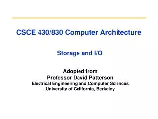
Disk Storage • Shift in focus from computation to communication and storage of information • E.g., Cray Research/Thinking Machines vs. Google/Yahoo • “The Computing Revolution” (1960s to 1980s) “The Information Age” (1990 to today) • Storage emphasizes reliability and scalability as well as cost-performance • What is “Software king” that determines which HW features actually used? • Operating System for storage • c.f. Compiler for processor
Disk Figure of Merit: Areal Density • Bits recorded along a track • Metric is Bits Per Inch (BPI) • Number of tracks per surface • Metric is Tracks Per Inch (TPI) • Disk designs brag about bit density per unit area • Metric is Bits Per Square Inch: Areal Density =BPI x TPI
Historical Perspective • 1956 IBM Ramac — early 1970s Winchester • Developed for mainframe computers, proprietary interfaces • Steady shrink in form factor: 27 in. to 14 in. • Form factor and capacity drives market more than performance • 1970s developments • 8” & 5.25” floppy disk form factor (microcode into mainframe) • Emergence of industry standard disk interfaces • Early 1980s: PCs and first generation workstations • Mid 1980s: Client/server computing • Centralized storage on file server • accelerates disk downsizing: 8 inch to 5.25 • Mass market disk drives become a reality • industry standards: SCSI, IPI, IDE • 5.25 inch to 3.5 inch drives for PCs, End of proprietary interfaces • 1900s: Laptops => 2.5 inch drives • 2000s: What new devices leading to new drives?
Future Disk Size and Performance • Continued advance in capacity (60%/yr) and bandwidth (40%/yr) • Slow improvement in seek, rotation (8%/yr) • Time to read whole disk Year Sequentially Randomly (1 sector/seek) 1990 4 minutes 6 hours 2000 12 minutes 1 week(!) 2006 56 minutes 3 weeks (SCSI) 2006 171 minutes 7 weeks (SATA)
Use Arrays of Small Disks? • Katz and Patterson asked in 1987: • “Can smaller disks be used to close gap in performance between disks and CPUs?” Conventional: 4 disk designs 3.5” 5.25” 10” 14” High End Low End Disk Array: 1 disk design 3.5”
Advantages of Small Formfactor Disk Drives Low cost/MB High MB/volume High MB/watt Low cost/Actuator Cost and Environmental Efficiencies
Replace Small Number of Large Disks with Large Number of Small Disks! (1988 Disks) IBM 3390K 20 GBytes 97 cu. ft. 3 KW 15 MB/s 600 I/Os/s 250 KHrs $250K x70 23 GBytes 11 cu. ft. 1 KW 120 MB/s 3900 IOs/s ??? Hrs $150K IBM 3.5" 0061 320 MBytes 0.1 cu. ft. 11 W 1.5 MB/s 55 I/Os/s 50 KHrs $2K Capacity Volume Power Data Rate I/O Rate MTTF Cost 9X 3X 8X 6X Disk Arrays have potential for large data and I/O rates, high MB per cu. ft., high MB per KW, but what about reliability?
Array Reliability • Reliability of N disks = Reliability of 1 Disk ÷ N • 50,000 Hours ÷ 70 disks = 700 hours • Disk system MTTF: Drops from 6 years to 1 month! • • Arrays (without redundancy) too unreliable to be useful! Hot spares support reconstruction in parallel with access: very high media availability can be achieved
CS252 Administrivia • Next week is project meetings • Should have “interesting” results by then • November 12 is Veterans’ Day Holiday • Schedule Monday Project meetings on Tuesday 1-3pm • Second midterm Tuesday Nov 20 in class • Focus on multiprocessor/multithreading issues • We’ll assume you’ll have worked through practice questions, i.e., be familiar with cache protocols
Redundant Arrays of (Inexpensive) Disks • Files are "striped" across multiple disks • Redundancy yields high data availability • Availability: service still provided to user, even if some components failed • Disks will still fail • Contents reconstructed from data redundantly stored in the array Capacity penalty to store redundant info Bandwidth penalty to update redundant info
Redundant Arrays of Inexpensive DisksRAID 1: Disk Mirroring/Shadowing recovery group • • Each disk is fully duplicated onto its “mirror” • Very high availability can be achieved • • Bandwidth sacrifice on write: • Logical write = two physical writes • • Reads may be optimized • • Most expensive solution: 100% capacity overhead • (RAID 2 not interesting, so skip)
10010011 11001101 10010011 . . . P 1 0 1 0 0 0 1 1 1 1 0 0 1 1 0 1 1 0 1 0 0 0 1 1 1 1 0 0 1 1 0 1 logical record Striped physical records Redundant Array of Inexpensive Disks RAID 3: Parity Disk P contains sum of other disks per stripe mod 2 (“parity”) If disk fails, subtract P from sum of other disks to find missing information
RAID 3 • Sum computed across recovery group to protect against hard disk failures, stored in P disk • Logically, a single high capacity, high transfer rate disk: good for large transfers • Wider arrays reduce capacity costs, but decreases availability • 33% capacity cost for parity if 3 data disks and 1 parity disk
Inspiration for RAID 4 • RAID 3 relies on parity disk to discover errors on Read • But every sector has an error detection field • To catch errors on read, rely on error detection field vs. the parity disk • Allows independent reads to different disks simultaneously
Stripe Redundant Arrays of Inexpensive Disks RAID 4: High I/O Rate Parity Increasing Logical Disk Address D0 D1 D2 D3 P Insides of 5 disks D7 P D4 D5 D6 D8 D9 D10 P D11 Example: small read D0 & D5, large write D12-D15 D12 D13 P D14 D15 D16 D17 D18 D19 P D20 D21 D22 D23 P . . . . . . . . . . . . . . . Disk Columns
D0 D1 D2 D3 P D7 P D4 D5 D6 Inspiration for RAID 5 • RAID 4 works well for small reads • Small writes (write to one disk): • Option 1: read other data disks, create new sum and write to Parity Disk • Option 2: since P has old sum, compare old data to new data, add the difference to P • Small writes are limited by Parity Disk: Write to D0, D5 both also write to P disk
Redundant Arrays of Inexpensive Disks RAID 5: High I/O Rate Interleaved Parity Increasing Logical Disk Addresses D0 D1 D2 D3 P Independent writes possible because of interleaved parity D4 D5 D6 P D7 D8 D9 P D10 D11 D12 P D13 D14 D15 Example: write to D0, D5 uses disks 0, 1, 3, 4 P D16 D17 D18 D19 D20 D21 D22 D23 P . . . . . . . . . . . . . . . Disk Columns
Problems of Disk Arrays: Small Writes RAID-5: Small Write Algorithm 1 Logical Write = 2 Physical Reads + 2 Physical Writes D0 D1 D2 D0' D3 P old data new data old parity (1. Read) (2. Read) XOR + + XOR (3. Write) (4. Write) D0' D1 D2 D3 P'
RAID 6: Recovering from 2 failures • Why > 1 failure recovery? • operator accidentally replaces the wrong disk during a failure • since disk bandwidth is growing more slowly than disk capacity, the MTT Repair a disk in a RAID system is increasing increases the chances of a 2nd failure during repair since takes longer • reading much more data during reconstruction meant increasing the chance of an uncorrectable media failure, which would result in data loss
Berkeley History: RAID-I • RAID-I (1989) • Consisted of a Sun 4/280 workstation with 128 MB of DRAM, four dual-string SCSI controllers, 28 5.25-inch SCSI disks and specialized disk striping software • Today RAID is $24 billion dollar industry, 80% nonPC disks sold in RAIDs
Summary: RAID Techniques: Goal was performance, popularity due to reliability of storage 1 0 0 1 0 0 1 1 1 0 0 1 0 0 1 1 • Disk Mirroring, Shadowing (RAID 1) Each disk is fully duplicated onto its "shadow" Logical write = two physical writes 100% capacity overhead 1 0 0 1 0 0 1 1 0 0 1 1 0 0 1 0 1 1 0 0 1 1 0 1 1 0 0 1 0 0 1 1 • Parity Data Bandwidth Array (RAID 3) Parity computed horizontally Logically a single high data bw disk • High I/O Rate Parity Array (RAID 5) Interleaved parity blocks Independent reads and writes Logical write = 2 reads + 2 writes
Response Time (ms) 300 200 100 0 0% Throughput (% total BW) Queue Proc IOC Device I/O Performance Metrics: Response Time vs. Throughput 100% Response time = Queue + Device Service time
I/O Benchmarks • For better or worse, benchmarks shape a field • Processor benchmarks classically aimed at response time for fixed sized problem • I/O benchmarks typically measure throughput, possibly with upper limit on response times (or 90% of response times) • Transaction Processing (TP) (or On-line TP=OLTP) • If bank computer fails when customer withdraw money, TP system guarantees account debited if customer gets $ & account unchanged if no $ • Airline reservation systems & banks use TP • Atomic transactions make this work • Classic metric is Transactions Per Second (TPS)
I/O Benchmarks: Transaction Processing • Early 1980s great interest in OLTP • Expecting demand for high TPS (e.g., ATM machines, credit cards) • Tandem’s success implied medium range OLTP expands • Each vendor picked own conditions for TPS claims, report only CPU times with widely different I/O • Conflicting claims led to disbelief of all benchmarks chaos • 1984 Jim Gray (Tandem) distributed paper to Tandem + 19 in other companies propose standard benchmark • Published “A measure of transaction processing power,” Datamation, 1985 by Anonymous et. al • To indicate that this was effort of large group • To avoid delays of legal department of each author’s firm • Still get mail at Tandem to author “Anonymous” • Led to Transaction Processing Council in 1988 • www.tpc.org
I/O Benchmarks: TP1 by Anon et. al • DebitCredit Scalability: size of account, branch, teller, history function of throughput TPS Number of ATMs Account-file size 10 1,000 0.1 GB 100 10,000 1.0 GB 1,000 100,000 10.0 GB 10,000 1,000,000 100.0 GB • Each input TPS =>100,000 account records, 10 branches, 100 ATMs • Accounts must grow since a person is not likely to use the bank more frequently just because the bank has a faster computer! • Response time: 95% transactions take ≤ 1 second • Report price (initial purchase price + 5 year maintenance = cost of ownership) • Hire auditor to certify results
Unusual Characteristics of TPC • Price is included in the benchmarks • cost of HW, SW, and 5-year maintenance agreements included price-performance as well as performance • The data set generally must scale in size as the throughput increases • trying to model real systems, demand on system and size of the data stored in it increase together • The benchmark results are audited • Must be approved by certified TPC auditor, who enforces TPC rules only fair results are submitted • Throughput is the performance metric but response times are limited • eg, TPC-C: 90% transaction response times < 5 seconds • An independent organization maintains the benchmarks • COO ballots on changes, meetings, to settle disputes...
I/O Benchmarks via SPEC • SFS 3.0 Attempt by NFS companies to agree on standard benchmark • Run on multiple clients & networks (to prevent bottlenecks) • Same caching policy in all clients • Reads: 85% full block & 15% partial blocks • Writes: 50% full block & 50% partial blocks • Average response time: 40 ms • Scaling: for every 100 NFS ops/sec, increase capacity 1GB • Results: plot of server load (throughput) vs. response time & number of users • Assumes: 1 user => 10 NFS ops/sec • 3.0 for NSF 3.0 • Added SPECMail (mailserver), SPECWeb (webserver) benchmarks
2005 Example SPEC SFS Result: NetApp FAS3050c NFS servers • 2.8 GHz Pentium Xeon microprocessors, 2 GB of DRAM per processor, 1GB of Non-volatile memory per system • 4 FDDI networks; 32 NFS Daemons, 24 GB file size • 168 fibre channel disks: 72 GB, 15000 RPM, 2 or 4 FC controllers
Flash: The future of disks? • Advent of digital cameras, mp3 players, has driven market for low-cost non-volatile flash memory • Other promising technologies in development: phase-change RAM, magnetic RAM (core returns!), but flash has big lead • In 2007, several announcements of flash-based disk replacement for laptops/servers • SanDisk, Samsung, I/O fusion, … • Flash drive advantages: • Lower power (no moving parts) • Much faster seek time, 100X IOs per second (no moving parts) • Greater reliability (no moving parts) • Lower noise (no moving parts) • Flash disadvantages • Cost (20-100x disk cost/GB) • Slow writes with current design (competitive with disks) • write endurance - not an issue for most applications since use write-leveling to spread wear around blocks on chip • Potential benefit of flash hidden behind standard disk interface • Scope for massive rethinking of storage architecture if non-volatile moves into memory hierarchy and accessed via processor loads/stores not seek/read/write