Download
1 / 51
520 likes | 734 Vues
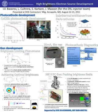
Ultra-High Brightness electron beams from laser driven plasma accelerators. Luca Serafini, INFN-Milano. ( A look at the particle beam beyond the source ). 6D Phase Space Density of beams produced by self-injection mechanisms (Brightness, Brilliance).

E N D
Ultra-High Brightness electron beams from laser driven plasma accelerators Luca Serafini, INFN-Milano (A look at the particle beam beyond the source) • 6D Phase Space Density of beams produced by self-injection mechanisms (Brightness, Brilliance) • Brightness Degradation due to Chromaticity blow-out in ultra-focused beams (Dp/p> 1% is a danger) • Ultra-high brightness in step density gradient plasma injectors • Fs to As pulses of Coherent X-rays (the AOFEL)
Vittoria Petrillo Università degli Studi, Milano (Italy) Alberto Bacci, Andrea R. Rossi, Luca Serafini, Paolo Tomassini INFN, Milano (Italy) Carlo Benedetti, Pasquale Londrillo, Andrea Sgattoni, Giorgio Turchetti Università and INFN Bologna (Italy)
Figures of Merit for Particle Beams Brightness and Brilliance 5D and 6D phase space density
1018 1017 AOFEL I [kA] 1016 1015 1014 1013 n[m] Self-Inj SPARX X-ray FEL @ 1 pC SPARC Photo-injectors The Brightness Chart [A/(m.rad)2]
1017 Bn 1016 1015 1014 Dg/g[0.1%] AOFEL X-ray FEL @ 1 pC SPARX Self-Inj Ext-Inj SPARC The 6D Brilliance Chart [A/((m.rad)20.1%)]
+ + + + + + + + + + + + + + + + + + + + + + + + + + + + + + + + + + + + + + + + + + + + + + + + + + Physical Principles of the Plasma Wakefield Accelerator Courtesy of T. Katsouleas Plasma acceleration experiments with SPARC/X e- beams • Space charge of drive beam displaces plasma electrons - - - - - - - - - - - - - - - - - - - - - - - - - - - - - - - - - - - - - - - - - - - - - - - - - - - - - - - - - - - - - - - - - - - - - - - - - - + + + - - - - - - - - - + - - + + + + + - + + + + + - + + + + + + + - - - - + + + + + + + + + + + + + + + - - - - - - - - - - - electron beam - - - - - - - - - - - - - - - - - - - - - - - - - - - - - - - - - - - - - - - - - - - - - - - - - - - - Ez • Plasma ions exert restoring force => Space charge oscillations • Wake Phase Velocity = Beam Velocity (like wake on a boat) • Wake amplitude • Transformer ratio
Self-Injection beams seem to have low phase space density but high rapidity (suited for relativistic piston applications)
x envelope and emittance free diffraction in vacuum RETAR (A. Rossi) no description of plasma vacuum interface
Transverse and longitudinal phase and configuration spaces @ 1 cm
Transverse and longitudinal phase and configuration spaces @ 92 cm
Emittance Dilution due to Chromatic Effects on a beam emerging from a focus of spot size s0, drifting to a distance d SPARC en=1 mm.mrad, s0= 200 m, g=300, Dg/g=0.6%, d=10 m Den =0.005 mm.mrad Self-Inj en=2 mm.mrad, s0= 1 m, g=2000, Dg/g=2%, d=1 m Den =40 mm.mrad
Space charge energy spread No Space charge energy spread
No Space charge No energy spread SPARC beam Space charge energy spread
How to measure this emittance blow-up? No trace on beam envelope… energy selection?
beam plasma acceleration focusing emittance Beam-plasma wavelength betatron length laminarity parameter SPARC 640 m transition spot-size SPARX 580 m AOFEL 3 m Bubble-self.inj. 80-150 m
AOFEL CO2 envelope CO2 focus r m] TiSa envelope TiSa pulse e- beam plasma Lsat=10LG=1.3 mm (=0.002) Z [m]
AOFEL • injection by longitudinal nonlinear breaking of the wave • at a density downramp looks one of the most promising • since it can produce e-beams having both low energy • spread and low transverse emittance. • electromagnetic undulator made by a laser pulse • counter propagating respect to the electron beam
First stage:LWFA with a gas jet modulated in areas of different densities with sharp density gradients.
Longitudinal phase space and density profile Selection of best part in the bunch: 40 pC in 2 fs (600 nm) projected rms n = 0.7 m <> <>
Third stage Numerical Modelling First stage Formation of the plasma Formation of the bunch Acceleration stage Transition Plasma-undulator Beam-CO2 laser Interaction FEL instability Genesis 1.3 EURA VORPAL C. Nieter J. R. Cary J.Comp.Phys. 196 448 (2004) New results by ALADYN Astra Retar Secondstage
Second stage: Transition from the plasma to the interaction area with the e.m. undulator (analysis by ASTRA) With space charge Without space charge
FEL interaction with a e.m. undulator = 1.35nm Pierce Parameter IA=17 103 Amp Ideal 1d model Erad=rEbeam 4pr) Lg1d=lu/( Three-dimensional model Lg=lu(1+h) /(31/24pr)
<1 , <1 <1
Requirements for the growth Generalized Pellegrini criterion
1.3 1.15 106 m-1 20 kA 50 5 X 10⁻⁶ m r=3 10-3
Lg1d=76 mm sz=0.2 mm Lg=200 mm
Transverse coherence d= Lsat*l/sx= 10*Lg*l/sx = 10*200 10-6*10-9/5 10-6=0.4 mm Longitudinal coherence Lc=l/(4pr ) (1+h) =0.04 mm 1 spike each 10 Lc
Superradiant structure Third stage: FEL radiation l=lu(1+aw2)/4g2by uploading the particles by VORPAL Monochromatic pulse Single spike structure 0.1 mm=330 as
25 micron 25 micron Laser requirements: 250 GW for 5 mm R=30 mm E=4.16J
I=31 KA sz=1.5 mm sx=0.6 um en=0.1 mm g=45 DE/E=0.3% a0=0.8 l=0.162 nm
Conclusions • All optical free-electron laser are possible with e-beam produced by LWFA in density downramp + electromagnetic undulators • Characteristics of radiation: small energy/pulse, quasi transverse coherent, very short pulse, longitudinal coherence, monochromaticity • Injection of the beam, control of the exit from the plasma, requirements of power and structure of the e. m. undulator
Conclusions • Beams produced by Self-Injection in the bubble regime look affected by strong chromaticity: serious emittance dilution after the source, loss of beam brightness • Possible cures: prompt focusing in mm (plasma lenses?), energy selection (charge loss), emittance compensation schemes? • Maximum brightness with step downramp density injection (1D mech., localized injection) Needs new targets, shock wave gas jets • AOFEL: table top X-FEL delivering fs to as quasi-coherent bright X-ray pulses
Scattered photons in collision • Scattered flux • Luminosity as in HEP collisions • Many photons, electrons • Focus tightly • Short laser pulse; <few psec (depth of focus) Thomson X-section
This last group tries to realize the scheme proposed by Gruener et al. (1.74 GeV, 160 kA, 1mm mrad, DE/E=0.1%, sx=30 mm) where an electron beam generated by LWFA in the bubble regime is driven in a static undulator lu=5 mm, l=0.25nm, Lsat=5m, Lrad=4fs,Psat=58 GW,
The technology of ultra short, high power lasers has permitted the production and the study of high-brightness, stable, low divergence, quasi mono-energetic electron beams by LWFA. • These beams are now an experimental reality (for instance: Faure et al.,Leemans et al., Jaroszinski et. al, Geddes et al., ecc.) • and can be used in applications for driving Free-electron lasers Last experimental results, see, for instance: • J.Osterhoff et al. PRL 101 085002 (2008) • (mono-energetic fraction: 10 pC@200 MeV, divergence=2.1 mrad FWHM) • Koyama, Hosokai 20 pC @ 100 MeV and density downramp • N. Hafz, Jongmin Lee , Nature photonics • THCAU05 FEL Conf 2008
Lg=10.1 x (g sx2/3/I1/3)x(lw/K0/JJ2)1/3 CO2 envelope Ti:Sa envelope Ti:Sa pulse electron beam Gas jet Lsat≈10 Lg AOFEL
GENESIS Simulations starting from actual phase space from VORPAL (with oversampling) =2.5 m (CO2 laser focus closer to plasma) Simulation with real bunch After 1 mm : 0.2 GW in 200 attoseconds Lbeff < 2 Lc
GENESIS Simulations for laser undulator at 1 m to radiate at 1 Angstrom Peak power 100 MW in 100 attoseconds Average power (Lsat~500 m, Psat~10 MW) Coherence Time duration Simulation with real bunch =3.5 m Field