DAQ+trigger operation during 2008 run
260 likes | 283 Vues
This document provides an overview of the DAQ+Trigger operation and additional features during the 2008 run at the University of Pisa and INFN. It covers topics such as data throughput and storage, slow control and alarms, trigger selection criteria, DRS system performances, and improvements for the 2009 run.

DAQ+trigger operation during 2008 run
E N D
Presentation Transcript
DAQ+trigger operationduring 2008 run D. Nicolò University of Pisa & INFN, Pisa
Outlook • DAQ • Data throughput & storage • Additional features • The slow control & alarms • Trigger • Selection criteria • Efficiency & background rejection • Rates & Livetime • DRS system • DRS2/3 performances • DRS4 design • Improvements for 2009 run DAQ+Trigger operation
Data throughput and storage • Event & data rate • 6.5 ev/s, ~9 MB/s (@normal run) • max. 30 ev/s (limited by VME readout & DRS2 calibration) current %Live ~ 80% • Data write to online disk • 2000 events/run ~3 GB file size (smaller for calibration runs) • occupancy ~ 1 TB/d 100 TB/y (to be offline suppressed x3) • Disk available with 2TB capability • buffer for 2 days • Data storage & monitoring • Lazy Logger process to • automatic copy to offline cluster ( total 100 TB HD) • gzip Midas data files (x0.5 compression) • Offline histos available soon afterwards (~ 10 min after Run stop) DAQ+Trigger operation
Offlinecheck: an example DAQ+Trigger operation
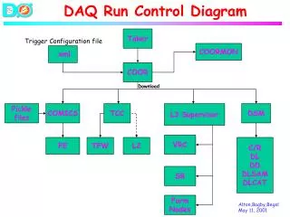
DAQ features • Automatic stop • Maximum event number completion data size • Run batch to be started from shell • Runsubmit xml script • Run parameters (#events, trigger operation, …) loaded to the online database (ODB) • System running smoothly • Major troubles • Event “mismatch” • FE hangs up • FE still busy at run start DAQ+Trigger operation
MSCB slow control • 13 Ethernet “Submasters” • 8 SCS-2000 units each with up to 64 I/O • Control of detector behaviour • Newly added features • Separator HV • Beam shutter (beam on-off) • Data recorder in the MIDAS history files available through the WEB page • Alarm generation in the case of failures DAQ+Trigger operation
Selection criteria QTL QTH DWW DWN MeV g -energy e+-g direction e+-g timing trig.# name conditions 0 MEGQSUM> QTH && D <DN && |T|<TWN 1 MEG-QQSUM>QTL && D <DN && |T|<TWN 2 MEG-DQSUM> QTH && D < DW && |T|<TWN 3 MEG-TQSUM> QTH && D <DN && |T|< TWW 4 RD-narrow QSUM> QTL && |T|<TWN 5 RD-wideQSUM> QTL && |T|<TWW
On-line Eγresolution 55 MeVγ-line from π0-decay σ= 3.8% 45 MeV threshold (@4s from signal)
Eγefficiency • Obtained from the ratio SH(Eγ)/SL(Eγ) off-line energy spectra normalizated by using proton current info 0.5 counts/s/MeV FWHM = 9,4% at 45 MeV Threshold smearing mainly due to on-line energy resolution ε 99% DAQ+Trigger operation
Δteγefficiency |ΔT (LXe-TC)| < 10 ns Spectrum expected to be flat (accidental background) σ(ΔT) = (3.8±0.1) ns εΔT~ 99% (σt = 2.5 ns on each) B(p,g)C (background free!) TRG type 0 signal • online • offline Δt (ns) DAQ+Trigger operation
e+-γdirection • γ-position by max PMT in LXe • e+-position by charge asymmetry in TC (TC fibers not included yet) • association LUT based on MC Cross-check with the data (Radiative Decay sample) a) Searchfore+ “good quality” track candidates (χ2, matchedextrapolationtoTC) b) Tracka backward hypotheticalγfromdecay vertex; c) γhitpositionLXe PMT index; d) LXe PMT indexsearchfore+-hit on TCintheLUT Work in progress DAQ+Trigger operation
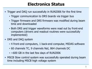
DRS in 2008 • DRS2 • All analog channels equipped • 848 LXe PMTs • 60 TC PMTs • 1728 DC (anode + vernier) • 0.5 – 1.6 GHz sampling speed • Voltage non-linearity calibration in FE • Temperature dependence 1.4%/oC • DRS3 • 4 cards available • NIM TC DTD outputs • Voltage linearity (0 : 1 V) • Ghostpulseproblemtobefixedin DRS4 DAQ+Trigger operation
DRS2 linearity • Cell-dependent non-linear responsefunctionapplied • Differential linearity restoredat2% DRS amplitude TRG amplitude DAQ+Trigger operation
Timing • Testdonebysplitting the same TC pulse to2 channels of thesame chip • Plotof(t0-t1)/2 negligible with respect to detector resolution Different domino waves running on different chips chip-to-chip timing needs calibration critical issue DRS2 DRS3 rms = 9.4 ps rms = 6.6 ps DAQ+Trigger operation
DRS4 design • Same VME board as former versions • New mezzanine card • Single ended differential input (common-noise suppression) • Memory doubled • (up to 3.2 GHz sampling or 2x wider time window) • All domino waves running synchronously (ref. CLK jitter < 10 ps) • New DC supply at 2.5 V • compatibility with FPGA LVDS ref. CLK DAQ+Trigger operation
DRS4 Schedule • Add special clock chip for in-situ calibration • First prototype DRS4 mezzanine board end of February • Extend mezzanine firmware: Store calibration in EEPROM, channel cascading (needed for 3.2 GSPS operation), in-situ timing calibration • Test in area (March) with cosmics • Start mass production: 5-6 weeks ( end of May) • Deploy DRS4 boards in area: June • Use July as contingency MEG weekly meeting
Further improvements in 2009 • Hardware • Test of the electronics chain by injecting a test pulse from splitter output • DAQ • No calibration needed for DRS4 DAQ speed-up • Max. rate 30 50 ev/s, %Live 80% 90% • Reduce dead time (6.5%) due to Start/Stop procedure • Subrun • Fix residual troubles • Trigger • Optimization of dynamic range • might be a concern if LXe light yield increases • DRS4 DAQ+Trigger operation
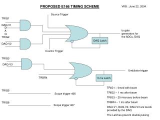
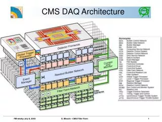
‘cave’ pE5 area Trigger Trigger Trigger Trigger clock start stop sync Front-End PCs Master PC (Linux) PC (Linux) PC (Linux) PC (Linux) Run start Run stop Trigger config PC (Linux) DRS PC (Linux) DRS Busy Error PC (Linux) DRS DRS PC (Linux) DRS PC (Linux) DRS 20 MHz clock PC (Linux) Hit registers Event builder PC (Linux) PC (Linux) Gigabit Ethernet Trigger signal Event number Trigger type PC (Linux) PC (Linux) On-line farm storage System overview Ancillary system 4 crates 5 crates DAQ+Trigger operation
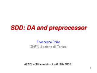
DAQ scheme trigger & trigger type & event # LSB busy TRG1 TRG2 TRG3 TRG9 DRS4 DRS5 DRS6 DRS7 DRS8 internal trigger & busy SYSTEM01 SYSTEM02 SYSTEM03 SYSTEM04 SYSTEM05 SYSTEM06 SYSTEM07 SYSTEM08 SYSTEM09 EventBuilder stop sequence start sequence SYSTEM Logger DAQ+Trigger operation
HW event # HW event # HW event # 50 50 50 50 50 50 50 50 50 50 50 50 50 50 50 50 50 50 52 52 52 52 52 52 52 52 52 52 52 52 52 52 51 52 52 52 51 51 51 51 51 51 51 51 51 51 51 51 51 51 51 51 SW serial # SW serial # SW serial # Event “mismatch” TRG1 TRG2 TRG3 TRG9 DRS4 DRS5 DRS6 DRS7 DRS8 SYSTEM01 SYSTEM02 SYSTEM03 SYSTEM04 SYSTEM05 SYSTEM06 SYSTEM07 SYSTEM08 SYSTEM09 Run stopped, error message returned by Event Builder
14 boards . . . Type2 Type2 Type2 Type2 Type2 Type2 14x 48 Type1 Type1 Type1 Type1 Type1 Type1 Type1 Type1 Type1 Type1 Type1 Type1 Type1 Type1 4 4 4 4 16 16 16 16 16 16 16 16 2 boards Inner face (216 PMTs) 2 x48 LXe 5+4+2 boards Side faces lat. (144x2 PMTs) 4x1 back (216 PMTs) 4x1 u/d (54x2 PMTs) 4x1 . . . The trigger tree 1 board 1 board 9 x 48 START STOP CLK SYNC 2 x48 1 board 8 boards . . . Bars (30x2 PMTs) Fibers (512APDs) 8x1 9x 48 TC 2 x48 4 boards 1 board Wires 64 channels 4x 48 DC 1x 48 1 board NaI+pre-shower 16 channels Aux Synchronous operation at 100 MHz CR counters 32 channels 2 boards
Rate monitor DAQ+Trigger operation