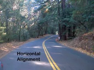
HORIZONTAL ALIGNMENT
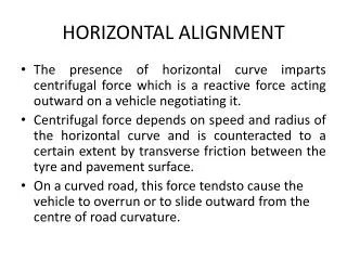
HORIZONTAL ALIGNMENT . The presence of horizontal curve imparts centrifugal force which is a reactive force acting outward on a vehicle negotiating it.

HORIZONTAL ALIGNMENT
E N D
Presentation Transcript
HORIZONTAL ALIGNMENT • The presence of horizontal curve imparts centrifugal force which is a reactive force acting outward on a vehicle negotiating it. • Centrifugal force depends on speed and radius of the horizontal curve and is counteracted to a certain extent by transverse friction between the tyre and pavement surface. • On a curved road, this force tendstocause the vehicle to overrun or to slide outward from the centre of road curvature.
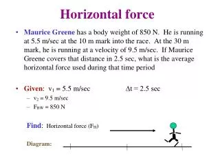
FORCES ACTING ON A VEHICLE TAKING A HORIZONTAL CURVE centrifugal force (P) acting outward, weight of the vehicle (W) acting downward, reaction of the ground on the wheels (RA and RB). The centrifugal force and the weight is assumed to be from the centre of gravity which is at h units above the ground.. Let the wheel base be assumed as b units. centrifugal force P in kg/m2 is given by P =Wv2/gR where W is the weight of the vehicle in kg, v is the speed of the vehicle in m=sec, g is the acceleration due to gravity in m=sec2 R is the radius of the curve in m The centrifugal ratio or the impact factor P/W is given by: P/W=v2/gR
centrifugal force -effects: • tendency to overturn the vehicle about the outer wheels • tendency for transverse skidding. Taking moments of the forces with respect to the outer wheel when the vehicle is justabout to over ride At the equilibrium overturning is possible when for safety the following condition must satisfy: else the vehicle will overturn at the horizontal curve The second tendency of the vehicle is for transverse skidding. i.e. When the centrifugal force P is greater than the maximum possible transverse skid resistance due to friction between the pavement surface and tyre.Thetransverse skid resistance where FA and FB is the fractional force at tyre A and B, RA and RB is the reaction at tyre A and B, f is the lateral coefficient of friction and W is the weight of the vehicle. This is counteracted by the centrifugal force(P), and equating: At equilibrium, when skidding takes place for safety the following condition must satisfy: else the vehicle will skid at the horizontal curve
Super-elevation • Super-elevation or cant or banking is the transverse slope provided at horizontal curve to counteract the centrifugal force, by raising the outer edge of the pavement with respect to the inner edge, throughout the length of the horizontal curve. • When the outer edge is raised, a component of the curve weight will be complimented in counteracting the effect of centrifugal force.
Analysis of forces acting on a vehicle while taking a horizontal curve with super elevation Forces acting on a vehicle on horizontal curve of radius R m at a speed of v m/sec2 P the centrifugal force acting horizontally out-wards through the center of gravity, W the weight of the vehicle acting down-wards through the center of gravity, and F the friction force between the wheels and the pavement, along the surface inward. At equilibrium, by resolving the forces parallel to the surface of the pavement we get, where W is the weight of the vehicle, P is the centrifugal force, f is the coefficient of friction, өis the transverse slope due to super elevation. Dividing by W cos ө, We have already derived an expression for P/W. By substituting this in above equation where, e is the rate of super elevation, f the coefficient of lateral friction 0.15, v the speed of the vehicle in m/sec2, R the radius of the curve in m and g = 9.8m/sec2.
Three specific cases that can arise from equation e + f =v2/gR : If there is no friction due to some practical reasons, then f = 0 and equation becomes e = v2 /gR. This results in the situation where the pressure on the outer and inner wheels are same; requiring very high super-elevation e. If there is no super-elevation provided due to some practical reasons, then e = 0 and equation becomes f = v2/gR. This results in a very high coefficient of friction. 3 If e = 0 and f = 0.15 then for safe travelling speed from equation is given by vb = √fgR where vbis the restricted speed.
Guidelines on super-elevation • While designing the various elements of the road like super elevation, we design it for a particular vehicle called design vehicle which has some standard weight and dimensions. But in the actual case, the road has to cater for mixed traffic. Different vehicles with different dimensions and varying speeds ply on the road. • For example, in the case of a heavily loaded truck with high centre of gravity and low speed, super-elevation should be less, otherwise chances of toppling are more. Taking into practical considerations of all such situations, IRC has given some guidelines about the maximum and minimum super-elevation etc..
Design of super-elevation • For fast moving vehicles, providing higher super-elevation without considering coefficient of friction is safe, i.e.centrifugal force is fully counteracted by the weight of the vehicle or super-elevation. For slow moving vehicles,providing lower super-elevation considering coefficient of friction is safe, i.e.centrifugal force is counteracted by superelevation and coefficient of friction . • IRC suggests following design procedure:
Maximum and minimum super-elevation • Depends on (a) slow moving vehicle and (b) heavy loaded trucks with high CG. IRC specifies a maximum super-elevation of 7 percent for plain and rolling terrain, while that of hilly terrain is 10 percent and urban road is 4 percent. The minimum super elevation is 2-4 percent for drainage purpose, especially for largeradius of the horizontal curve.
Attainment of super-elevation • Elimination of the crown of the cambered section by: (a) rotating the outer edge about the crown : The outer half of the cross slope is rotated about the crown at a desired rate such that this surface falls on the same plane as the inner half. (b) shifting the position of the crown: This method is also known as diagonal crown method. Here the position of the crown is progressively shifted outwards, thus increasing the width of the inner half of cross section progressively. 2. Rotation of the pavement cross section to attain full super elevation by: There are two methods of attaining super-elevation by rotating the pavement (a) rotation about the center line : The pavement is rotated such that the inner edge is depressed and the outer edge is raised both by half the total amount of super-elevation, i.e., by E=2 with respect to the centre. (b) rotation about the inner edge: Here the pavement is rotated raising the outer edge as well as the centre such that the outer edge is raised by the full amount of superelevation with respect to the inner edge.
Radius of Horizontal Curve • The radius of the horizontal curve is an important design aspect of the geometric design. The maximum comfortable speed on a horizontal curve depends on the radius of the curve. Although it is possible to design the curve with maximum super-elevation and coefficient of friction, it is not desirable because re-alignment would be required if the design speed is increased in future. Therefore, a ruling minimum radius R ruling can be derived by assuming maximum super-elevation and coefficient of friction. Ideally, the radius of the curve should be higher than Rruling. However, very large curves are also not desirable. Setting out large curves in the field becomes difficult. In addition, it also enhances driving strain
Extra widening Extra widening refers to the additional width of carriageway that is required on a curved section of a road over and above that required on a straight alignment. This widening is done due to two reasons: The first and most important is the additional width required for a vehicle taking a horizontal curve and the second is due to the tendency of the drivers to ply away from the edge of the carriage way as they drive on a curve. The first is referred as the mechanical widening and the second is called the psychological widening.
Mechanical widening • The reasons for the mechanical widening are: When a vehicle negotiates a horizontal curve, the rear wheels follow a path of shorter radius than the front wheels. This phenomenon is called off tracking, and has the effect of increasing the effective width of a road space required by the vehicle. • Therefore, to provide the same clearance between vehicles travelling in opposite direction on curved roads as is provided on straight sections, there must be extra width of carriageway available. This is an important factor when high proportion of vehicles are using the road. Trailer trucks also need extra carriageway, depending on the type of joint. In addition speeds higher than the design speed causes transverse skidding which requires additional width for safety purpose.
The expression for extra width can be derived from the simple geometry of a vehicle at a horizontal curve as shown in figure Let R1 is the radius of the outer track line of the rear wheel, R2 is the radius of the outer track line of the front wheel l is the distance between the front and rear wheel, n is the number of lanes, then the mechanical widening
Psychological widening • Widening of pavements has to be done for some psychological reasons also. There is a tendency for the drivers to drive close to the edges of the pavement on curves. Some extra space is to be provided for more clearance for the crossing and overtaking operations on curves. IRC proposed an empirical relation for the psychological widening at horizontal curves Therefore, the total widening needed at a horizontal curve :
Transition curve Transition curve is provided to change the horizontal alignment from straight to circular curve gradually and has a radius which decreases from infinity at the straight end (tangent point) to the desired radius of the circular curve at the other end (curve point) The objectives for providing transition curve : 1. to introduce gradually the centrifugal force between the tangent point and the beginning of the circular curve, avoiding sudden jerk on the vehicle.This increases the comfort of passengers. 2. to enable the driver turn the steering gradually for his own comfort and security, 3. to provide gradual introduction of super elevation, and 4. to provide gradual introduction of extra widening. 5. to enhance the aesthetic appearance of the road.
Type of transition curve • Different types of transition curves are spiral or clothoid, cubic parabola, and Lemniscate. IRC recommends spiral as the transition curve because: 1. it fulffills the requirement of an ideal transition curve, that is; (a) rate of change or centrifugal acceleration is consistent (smooth) and (b) radius of the transition curve is infinity at the straight edge and changes to R at the curve point (Ls ᾳ 1/R) and calculation and field implementation is very easy.
length of the transition curve • The length of the transition curve should be determined as the maximum of the following three criteria: • rate of change of centrifugal acceleration, • rate of change of super-elevation, • an empirical formula given by IRC.
Setback Distance • Setback distance m or the clearance distance is the distance required from the center-line of a horizontal curveto an obstruction on the inner side of the curve to provide adequate sight distance at a horizontal curve. The setback distance depends on: 1. sight distance (OSD, ISD and OSD), 2. radius of the curve, 3. length of the curve.
Curve Resistance • When the vehicle negotiates a horizontal curve, the direction of rotation of the front and the rear wheels are different. The front wheels are turned to move the vehicle along the curve, whereas the rear wheels seldom turn. The rear wheels exert a tractive force T in the PQ direction . The tractive force available on the front wheels is Tcos in the PS direction as shown in the figure. This is less than the actual tractive force, T applied. Hence, the loss of tractive force for a vehicle to negotiate a horizontal curve is: