Download
1 / 61
610 likes | 821 Vues
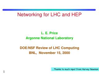
Currently and Advanced Pixel designs for HEP. Patrick Pangaud Centre de Physique des Particules de Marseille C.P.P.M 163 , avenue de Luminy Case 902 13288 Marseille cedex 09 France pangaud@cppm.in2p3.fr. Hybrid pixels sensor for High Energy Physics. IBM 130nm : FEI4 development

E N D
Patrick Pangaud - CPPM-IN2P3-CNRS Currently and Advanced Pixel designs for HEP Patrick Pangaud Centre de Physique des Particules de Marseille C.P.P.M 163, avenue de Luminy Case 902 13288 Marseille cedex 09 France pangaud@cppm.in2p3.fr
Patrick Pangaud - CPPM-IN2P3-CNRS Hybrid pixels sensor for High Energy Physics IBM 130nm : FEI4 development TSMC 65nm : FEI5 develpment TEZZARON 3D 130nm: FETC4 developments HVCMOS development
Patrick Pangaud - CPPM-IN2P3-CNRS Hybrid Pixels Detector for LHC/HL-LHC at CERN • Whatever will be discovered in next years at LHC, need much data to understand what has been discovered. • Higher luminosity allows extending discovery/studies to • higher masses • processes of lower cross-section • LHC has plans of upgrade by increasing luminosity to collect ultimately ~ 3000 fb-1 . • This will open new physics possibilities. LHC : Luminosity of 1034 cm-2.s-1 • HL-LHC expected 10 times more luminosity, more pixels, more ionizing particles, more … !!!
Patrick Pangaud - CPPM-IN2P3-CNRS Inner Tracking ATLAS detector Straw tubes Silicon strip Silicon pixel
Patrick Pangaud - CPPM-IN2P3-CNRS LHC and ATLAS upgrade Possible upgrade timeline 7 TeV →14 TeV → 5x1034cm-2s-1 luminosity leveling ∫ L dt 1x1034 → ~2x1034cm-2s-1 3000 fb-1 phase-2 → 1x1034cm-2s-1 ~300 fb-1 1027→ 2x1033cm-2s-1 phase-1 ~50 fb-1 phase-0 ~10 fb-1 2013/14 2018 ~2022 Year Now T. Kawamoto, TIPP2011, Chicago, USA
Patrick Pangaud - CPPM-IN2P3-CNRS ATLAS upgrade • LHC improves, bulk of luminosity with instantaneous luminosity beyond the • nominal luminosity for which the ATLAS detector was designed and built. • Technology improves, can build better performing detector now. • Detectors age, after the nominal integrated luminosity has been collected, • leading to deterioration of performance during the runs at higher luminosity. • It will take long time to study and build new detector • Installation has to be done during the limited number of long shut downs • Installation has to be planned to be prepared to the new running condition T. Kawamoto, TIPP2011, Chicago, USA
Patrick Pangaud - CPPM-IN2P3-CNRS Hybrid pixels sensor for High Energy Physics IBM 130nmFE-I4 development
50 μm Done : ATLAS/LHC (2008/2009) Under Production ATLAS/LHC upgrade project (2013-2014) FE-I3 CMOS technology : 250 nm 50 μm 400 μm FE-I4 CMOS technology : 130 nm 250 μm Participating institutes: Bonn: D. Arutinov, M. Barbero, T. Hemperek, A. Kruth, M. Karagounis. CPPM: D. Fougeron, M. Menouni. Genova: R. Beccherle, G. Darbo. LBNL: S. Dube, D. Elledge, M. Garcia-Sciveres, D. Gnani, A. Mekkaoui. Nikhef: V. Gromov, R. Kluit, J.D. Schipper Patrick Pangaud - CPPM-IN2P3-CNRS Hybrid Pixels Sensor for HEP The FE-I4 readout chip FE-I3 18 160 FE-I4
Patrick Pangaud - CPPM-IN2P3-CNRS FE-I4 : Motivation for Redesign of FE • Need for a new FE? • Smaller b-layer radius + potential luminosity increase • higher hit rate. • FE-I3 column-drain architecture saturated. • FE-I4 new digital architecture: local regional memories, stop moving hits around (unless RO). • FE-I4 has smaller pixel (reduced cross-section). • New technology: Higher integration density for digital circuits, rad-hard, availibility. FE-I3FE-I4 100 Inefficiency [%] sLHC 80 IBL 60 40 FE-I3 at r=3.7 cm! LHC 20 0 0 1 2 3 4 5 7 9 10 8 6 Hit prob. / DC The “inefficiency wall” 0.25 μm130 nm M. Backhaus, FEI4 course, Desy, Germany
Patrick Pangaud - CPPM-IN2P3-CNRS Future FE-I4-Based Module and Consequences for FE-I4 Flex 4 4 Sensor 3 1 2 FE-Chip 3 1 2 5 1) Big chip (periphery on one side of module). 2) Reduce size of periphery (2.8 mm2 mm). 3) Thin down FE chips (190 μm90 μm). 4) Thin down the sensor (250 μm 200 μm)? 5) Less cables (powering scheme)? • Increased active area: from less than 75 % to ~90 %: Reduced periphery; bigger IC; cost down for sLHC (main driver is flip-chip costs per chip). • No MCC: More digital functionality in the IC. • Power: Analog design for reduced currents; decrease of digital activity (digital logic sharing for neighbor pixels); new powering concepts. 8 metal layers [2 thick Alu.] power routing. challenging: power (routing, start-up), clk. distrib., simulation / management, yield M. Backhaus, FEI4 course, Desy, Germany
Patrick Pangaud - CPPM-IN2P3-CNRS Motivation for Redesign of FE • Need for a new FE? • Accommodate higher hit rate (smaller b-layer radius + luminosity increase) Architecture based on local memories (no column-drain mechanism). • Smaller pixel size: enhanced granularity and reduced cross-section. • Reduced periphery & bigger chip: higher active area fraction (<75% ~90%); cost down for sLHC (main driver is flip-chip, costs per chip). Big chip a challenge: power (routing, start-up), clk. distrib., yield… • Simple module: No Module Controller More digital functions into the FE. • Power efficient design & new concepts: Analog design for reduced currents; decrease of digital activity (digital logic sharing for neighbor pixels); new powering concepts. 8 metal layers [2 thick Alu.] Power routing. • New technology: • Higher integration density for digital circuits, radiation-hardness (no Enclosed Layout Transistor), availability on timescales of our experiments. M. Backhaus, FEI4 course, Desy, Germany
Patrick Pangaud - CPPM-IN2P3-CNRS 4-pixel region FE-I4 : architecture analog 1-pix pixel array: 336×80 pixels digital 4-pix DDC EODCL EOCHL DOB CMD DCD CLKGEN periphery Power Pads
Patrick Pangaud - CPPM-IN2P3-CNRS FE-I4 : Digital Region (simplified) • Receiving hit • Generate leading edge • Start ToT counter • Assign first free memory and latency counter • Generate trailing edge • Store ToT value • Check for trigger when latency counter finished • Indicate ready to read status (release token) - Hit Processing - ToT Counter - ToT Memory • Read memory - Latency Counter - Triggering/Readout • Release memory after read M. Backhaus, FEI4 course, Desy, Germany
Patrick Pangaud - CPPM-IN2P3-CNRS Hybrid pixels sensor for High Energy Physics TSMC 65nmFE-I5 development
For the HL-LHC (Phase 2) a new pixel detector is planned • 2 removable internal layers are planned ( 3.9 cm – 7.5 cm) • The event rate is high and the FE-I4 architecture is not adapted • The Total Dose is ~ 1GRad • A new design is required • Reduction of the pixel size for the inner layers • R&D : CMOS 65 nm, 3D, Monolithic design CMOS 65 nm is an attractive solution for the development of high-density readout IC. Patrick Pangaud - CPPM-IN2P3-CNRS 65nm motivations
Patrick Pangaud - CPPM-IN2P3-CNRS 65nm prototyping • TSMC 65 nm process allows good tolerance to SEU. • However the tolerance of TSMC-ARM digital cells have to be investigated for high dose level : 1000 Mrad Dose effect : Simulations are in progress to check if there are “sensitive” devices inside the Library DFF cell. • New designs are in development : • different structures of configuration memories, • IP blocs : ADC, Voltage reference • First submission of 65nm CMOS IP blocks (plus individual narrow test transistors) is foreseen at CPPM in June or September 2013.
Patrick Pangaud - CPPM-IN2P3-CNRS Hybrid pixels sensor for High Energy Physics Tezzaron 3-D 130nmFE-TC4 development
Improve spatial resolution Deal with an increasing counting rate Decrease pixel size • 50 μm FE-I3 , 250 nm 400 μm Technology shrinking Vertical stacking • 50 μm FE-I4 , 130nm • 50 μm FE-TC4 , 130 nm 250 μm 125 μm 3-D benefits : Pixel size reduction Functionalities splitting Technologies mixing ANALOG DIGITAL Patrick Pangaud - CPPM-IN2P3-CNRS 3-D motivations for ATLAS read-out chip upgrades First MPW run for High Energy Physics organized byFNAL with a consortium of 15 institutes. The proposed 3-D process combines : GLOBAL FOUNDRY 130nm technology TEZZARON 3D technology
HL LHC : high luminosity, high pile up, high dose To keep the tracker performance one need to improve pixel granularity : • reduce occupancy , improve resolution (and 2 tracks separation) , reduce inefficiencies in the readout. • Several ways for hybrid pixels detectors • move to higher density technologies like 65 nm (shrinking technology ) • move to 3D electronics with in-pixel TSVs(vertical stacking) • move to CMOS HV (where the sensor can be in the same circuit as the analog amplification) Patrick Pangaud - CPPM-IN2P3-CNRS Context : Pixel trackers for high luminosity 3D goal : Reduce pixel area without shrinking technology by association of 2 or more layers staked by 3D technologies. • Needs in-pixel communication between the 2 tiers small TSV • Main 3D advantage : Adequate techno selection for the various functions • Main 3D drawback : Not so easy at the moment 50 μm 250 μm FE-I4 CMOS 130 nm 50 μm 125 μm FE-TC4 CMOS 130 nm 2 layers
Patrick Pangaud - CPPM-IN2P3-CNRS 3D-IC Integration The Other Path for Scaling Source IBM http://www.research.ibm.com/journal/rd/526/knickerbocker.html • Moore’s law by scaling conventional CMOS involves huge investments. • 3D IC processes : An opportunity for another path towards continuing the scaling, involving less investments. • Like for conventional CMOS, infrastructures are needed to promote 3D-IC integration, making it available for prototyping at “reasonable” costs.
Patrick Pangaud - CPPM-IN2P3-CNRS Why 3-D ? More than Moore…
Patrick Pangaud - CPPM-IN2P3-CNRS 3-D methods : Through Silicon Vias
Patrick Pangaud - CPPM-IN2P3-CNRS 3-D methods : Bonding Choices
Patrick Pangaud - CPPM-IN2P3-CNRS Understanding the Basic Principles of 3-D Integration • Vias • Via First – done at foundry, lowest cost • Via last – after wafers are made, often done by third party vendors. • General movement in industry toward via first approach • Bonding options • Mechanical bond only, electrical connections later • Oxide to oxide bonding • Adhesive such as BCB • Mechanical and electrical connection formed together • CuSn Eutectic • CuCu Fusion • Direct Bond Interconnect – combination of oxide bonding and metal fusion • Thinning • Alignment
Patrick Pangaud - CPPM-IN2P3-CNRS 3-D methods : Areas of Interest to HEP • Major Markets being pursued by Industry for 3D integration • Pixel arrays for imaging • Memory • Microprocessors • FPGAs • … • 3-D Pixel arrays with high functionality and smaller form factor for particle tracking • 3-D bonding technology to replace bump bonds in hybrid pixel assemblies.
Form vias before transistors IBM, NEC, Elpida, OKI, Tohoku, DALSA…. Tezzaron, Ziptronix Chartered, TSMC, RPI, IMEC…….. Form transistors before vias Patrick Pangaud - CPPM-IN2P3-CNRS 3-D integration : Via First Approach • Through silicon Via formation is done either before or after CMOS devices (Front End of Line) processing
Zycube, IZM, Infineon, ASET… Samsung, IBM, MIT LL, RTI, RPI…. Notes: Vias take space away from all metal layers. The assembly process is streamlined if you don’t use a carrier wafer. Patrick Pangaud - CPPM-IN2P3-CNRS 3-D integration : Via Last Approach • Via last approach occurs after wafer fabrication and either before or after wafer bonding
Patrick Pangaud - CPPM-IN2P3-CNRS 3-D project steps • FEI4_P1 design : IBM 130nm, 8 metals • 14x61 "analogue" pixel matrix • Pixel size : 50x166µm • Rad-hard and SEU tolerance • FEC4_P1circuit : 2D Chartered 130nm, 8 metals • Pixel structure : identical to FEI4_P1 (due to schedule no optimization has been done) • Objectives : test Chartered technology (functionalities, performances, radiation…) • FEC4_P2circuit : 2D Chartered, 8 metals • Based on FEC4_P1 circuit, plus : • Optimization of transistors • New latches for irradiation tests • New PadRing strategy and ground/substrate separation • FEC4_P3: 2D Chartered, 8 metals but only 5 are used) • Smaller pixel size : 50µm x 125µm • Design of new sub-circuits and functionalities : • Analogue multiplexor and Triple redundancy memory • Calibration (pulse generator) • PLL • LVDS and ESD I/O Pads Submission / Test March 08 / Summer 08 February 09 / April 09 Nov 09 / Jan 10 Nov 10 / Nov 11
First 3-D design (MPW organized by FNAL) FE-TC4_P1 project Global Foundries 130 nm (5 metal levels) + Tezzaron One Tier for the analogue pixel part : 14x61 pixel matrix Pixel size : 50x166µm One Tier for the digital part Two versions have been designed : one dedicated for test, (FE-TC4-DS) one “FE-I4-like”.,(FE-TC4-DC) Patrick Pangaud - CPPM-IN2P3-CNRS 3-D project steps Submission / Test July 09 / now
Patrick Pangaud - CPPM-IN2P3-CNRS Tezzaron-Chartered 3-D technology Main characteristics : • 2 wafers (tier 1 and tier 2) are stacked face to face with Cu-Cu thermo-compression bonding • Via Middle technology : Super-Contacts (Through Silicon contacts) are formed before the BEOL of Chartered technology. • Wafer is thinned to access Super-Contacts • Chartered 130nm technology limited to 5 metal levels • Back-side metal for bonding (after thinning) Wafer to wafer bonding Bond interface layout One tier
sensor Back SideMetal Super Contact Tier 1 (thinnedwafer) M1 M2 M3 M4 M5 Bond Interface M6 M6 M5 M4 M3 M2 M1 Tier 2 Super Contact 3D consortium created in 2008 (with MAPS and Hybrid pixels communities) and 3D MPW run in 2009 Patrick Pangaud - CPPM-IN2P3-CNRS Tezzaron-Chartered (130nm) 3D run Main technology features • 130 nm • Large reticle (≈26 x 30 mm) • 6 metal levels (M6 is the bond interface) • Wafer to wafer, face to face bonding • TSV Vias 1.2 µm diameter with 3.8 µm recommended pitch (Via Middle Techno) • Bond interface : copper (regular pattern) • Upper tier thinned down to 10 µm
Patrick Pangaud - CPPM-IN2P3-CNRS Fermilab 3-D Multi-Project Run • Fermilab has planned a dedicated 3-D multi project run using Tezzaron for HEP during 2009 • There are 2 layers of electronics fabricated in the Chartered 0.13 um process, using only one set of masks. (Useful reticule size 15.5 x 26 mm) • The wafers are bonded face to face. ATLAS/SLHC Sub-part
The reticles contains : • the analog tier : FE-TC4-AE : Pixel matrix of 14 x 61 pixels , pixel size 50x166 µm. Analog tier is very close to FE-C4-P1 (GF version of FE-I4-P1) • 2 flavors of digital tier : • FE-TC4-DS : digital tier with simple read-out (one-bit latch/ pixel), dedicated for studying coupling between tiers • FE-TC4-DC : digital tier with complex readout “a la FEI4” (Bonn) • SEU3D : SEUless memory blocks • General Test structures : TSV + BI Daisy chain , transistors, etc… Patrick Pangaud - CPPM-IN2P3-CNRS FE-TC4-P1 Bonn/CPPM reticles
First 3D wafers with defects visible to the naked eye Patrick Pangaud - CPPM-IN2P3-CNRS Delay due to production difficulties • First 3D assemblies AE-DC and AE-DS arrived in September 2011 with damages. • First tests in 2011 : Analog tier, DC tier, DS tier tested separately in standard thicknesses (February 2011) • First 3D working chips in 2012 ! Analog tier completely removed during thinning + misalignment of bond interface between two tiers
Based on FE-C4_P1 chip + all adds for 3-D connection 2 possible ways for discriminator output read-out: • With the simple read-out part existing yet into the pixel • With the tier 2 (via the Bond Interface) Additional switch for read-out Input signal from sensorvia the Super-Contacts Bonding pad in Back-side metal Patrick Pangaud - CPPM-IN2P3-CNRS FE-TC4-AE analogue tier
Mean Noise versus dose 60 FE-TC4_AE_3 FE-C4_P1 FE-TC4_AE_2 50 FE-TC4_AE_1 40 Mean Noise (e-) 30 20 10 0 0,1 1 10 100 1000 Dose (MRad) Patrick Pangaud - CPPM-IN2P3-CNRS The analogue Tier is thinned. The output of the comparator can be read directly in the analog tier or in the digital tier via the bond interface (in the same time!) 3D Test results : FETC4_AE results • The 10 µm thick analog pixel behaves as un-thinned one . Noise < 100 e- rms
ANALOGUE DIGITAL Patrick Pangaud - CPPM-IN2P3-CNRS FE-TC4-DS digital tier for test • Analogue tier and digital tier are face to face (sensitive part facing digital part). • FE-TC4-DS : dedicated for parasitic coupling studies between the 2 tiers. • 3 functions : • Read the discriminator output • Generate noise (digital commutations) in front of 11 specific areas of the analogue pixel (preamplifier, feed-back, amplifier2, DAC…) • Test different shielding configurations. Analogue pixel layout : 11 specific areas
Patrick Pangaud - CPPM-IN2P3-CNRS 3D Test results : FE-TC4-AEDS chipAnalogue and Digital Simple tiers communicate !
The DS chip contains : • a simple readout system (one-bit latch/ pixel), a counter, • 11 DRUM cells (noise generators to study the coupling between tiers) which can be activated individually. Patrick Pangaud - CPPM-IN2P3-CNRS 3D Test results : FE-TC4-AEDS chipShielding studies with Digital Simple • Each DRUM cell layout is facing one specific area (sub-part) of the analog pixel. • To test the intra-pixel sensitivity. A simple way to generate noise and test the influence on the analogue Tier.
Moreover, to determine the best shielding strategy, different metal shielding have been implemented on the DS chip : Patrick Pangaud - CPPM-IN2P3-CNRS 3D Test results : FE-TC4-AEDS chipShielding studies with Digital Simple Shielding configuration depending on column numbers : • Col 0 and 1 => shield in Metal 3 and Metal 5 • Col 2, 3, 4, 5 => shield in Metal 5 • Col 6, 7, 8 => no shield • Col 9 and 10 => shield in Metal 3 • Col 11, 12, 13 => no shielded ShieldMetal 3and Metal 5 Shield Metal5 Shield Metal 3 NoShield No Shield
First try Comparison No Drums / All Drums • S curves measurements Patrick Pangaud - CPPM-IN2P3-CNRS 3D Test results : FE-TC4-AEDS chipShielding studies with Digital Simple • A shielding is necessary. • Shielding with only M3 is not enough efficient. • Metal 5 appears to be the best solution. 150 e- noise = 116 e- 250 e- 800 e- 350 e-
Patrick Pangaud - CPPM-IN2P3-CNRS 3D Test results : FE-TC4-AEDS chipShielding studies with Digital Simple • Studying the intra-pixel sensitivity • Each drum is separately activated. The noise is measured on column 7 (without any shield) (noise of 116e- with all drum OFF). • The most sensitive parts are those directly connected to the input (bump area, injection capacitor) : Not a big surprise but it confirms that the others parts are not sensitive to the digital tier. 350 e- 120 e- 121 e- 119 e- 124 e- 200 e- 120 e- 400 e- 500 e- 119 e- 119 e-
Digital Complex chip offers a complex read-out "A la FE-I4” (with 4 pixel regions). The FE-TC4-AEDC is fully tested by Bonn University : Patrick Pangaud - CPPM-IN2P3-CNRS 3D Test results : FE-TC4-AEDC chip • The AE tier and DC tier communicates wells. • The analogue performances are as expected. • The readout with TOT information has been tested and works as expected. Threshold~2400e- Noise~94e- The tuned threshold can reach a dispersion of 50e-.
Test procedure: • Inject charge to two pixels and read out only the pixel in between. • Cover the matrix with a 16 Step mask. • Configuration : Tuned threshold around ~ 2800 electrons (for the pixel in the middle) • The injection is increased until reach the crosstalk threshold for which the middle pixel is affected. Crosstalk threshold = Normal Threshold / Threshold Measured with crosstalk mask Patrick Pangaud - CPPM-IN2P3-CNRS 3D Test results : FE-TC4-AEDC chipStudy of crosstalk between pixel Inject 16 StepMask First step Read Inject
The crosstalk threshold is the same if the readout is done via the analog shift register or the digital shift register : • The main crosstalk path is on the analog tier only. • No addition of crosstalk through the digital tier is observed. Patrick Pangaud - CPPM-IN2P3-CNRS 3D Test results : FE-TC4-AEDC chipStudy of crosstalk between pixel Read analog tier Read digital tier Threshold ~31680 e- Threshold ~31810 e- Crosstalk threshold ~ 4,42% Crosstalk threshold ~ 4,40%
From the first 3D prototype made for the ATLAS Project, some test were done to measure TSV and Bond-Interface performance. The TSV (Through Silicon Via) consists of a vertical conductor, often referred to as “nail” or “plug”, entirely crossing the Si substrate of the stacked dies. Patrick Pangaud - CPPM-IN2P3-CNRS 3D Project : test structures Measure the TSV daisy chain(51520 tsv), to understand its electrical properties.
We measured 19 chips, which show good tsv daisy chain interconnection. Yielding ~84%. Single tsv resistance is . Agree with reference value <600mohm(Tezzaron report) Single tsv capacitance(metal-insulator-semiconductor) in inversion region is around 5.5fF. The calculated value is 3.6fF. In addition, we cannot measure accumulation region capacitance because ESD diodes limit bias voltage. The BI test results reveal some problems. Only 1 chip shows good interconnection. Perhaps the alignment issues and chip surface irregularities lead to these problems. Patrick Pangaud - CPPM-IN2P3-CNRS FE-TC4-P1 TSV and BI test
Patrick Pangaud - CPPM-IN2P3-CNRS Single 2D FE-C4_Px test results All prototypes showed excellent results • Un-tuned FEC4_P1 threshold dispersion around 200 e- • FEC4_P1 Noise lower than 100 e- rms • FEC4_P1 Power consumption 27µA/pixel Irradiation performed at CERN/PS facility (24 GeV protons)
Third 2D chip in Chartered 130nm ( submitted in 2011) : • Smaller pixel size (50µm x 166µm => 50µm x 125µm) • Design of new sub-parts : analogue buffer, analogue multiplexor …. • Radiation Hardness improvement (optimized latches, substrate separation, guard-ring…) • Tests under radiation at CERN/PS : • The test was made up to 650 MRads. • The chip resists well : • up to 300 MRadsfor the Analog Part • and up to the end of the campaign for the Digital Part. • The chip is not broken after irradiation, and works. • The Analog Part shows a good annealing recovering after 6 months (after irradiation: 78% of dead pixels, after 6 months of annealing: 18% of dead pixels). • The new small analog pixel is now completely ready for a next 3D integration. Patrick Pangaud - CPPM-IN2P3-CNRS FEC4-P3 test results under radiation
Patrick Pangaud - CPPM-IN2P3-CNRS FEC4-P3 : Analog behavior before protons beam At 0Mrad Sigma Threshold = 674 e- Mean Noise = 339 e- The nominal noise is 100e-, but we ever detected some excess noise by using the USBPix card (200e-)