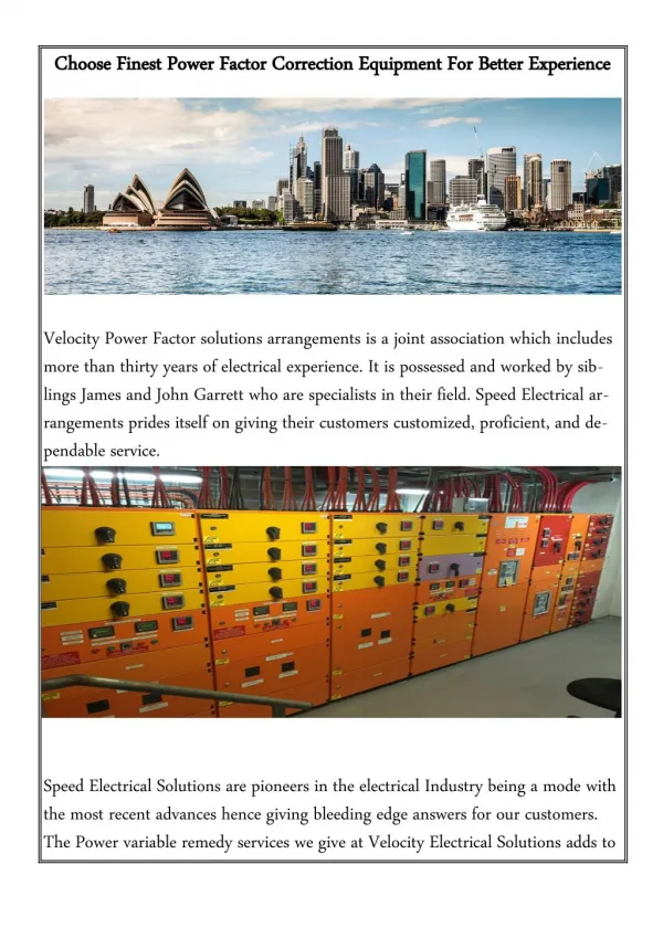

POWER FACTOR CORRECTION WITHIN INDUSTRIAL SITES
E N D
Presentation Transcript
POWER FACTOR CORRECTION WITHIN INDUSTRIAL SITES EXPERIENCES REGARDING PQ AND EMC IBERDROLA DISTRIBUCIÓN ELÉCTRICA F. Ferrandis
Industrial Compensation vs Distribution Network Compensation • Common practice both in distribution networks and industrial facilities... • ... But different reasons... • Utilities: Technical (system capacity, efficiency, voltage drops), economic (line losses, infrastructure costs) • Customers: Avoid penalties, existing space
Industrial Compensation vs Distribution Network Compensation • ... And also different problems... • Utilities: Tipically maintenance problems (capacitors & circuit breakers) • Customers: Serious problems caused by their own capacitor banks • Harmonics • Others: • voltage variations; interharmonics; high frequency surges; EMC problems
Customer facilities: problems in reactive power compensation at MV/HV • Might be the cheapest for Q > 1 MVAr • Usually: • Without regulation • Always connected • Connection through fuses (no circuit breakers) • Predominantly reactive system very little damping higher resonance at high order frequency • Two common configurations: • Capacitor banks connected directly at the PCC • HV customers with capacitor banks connected at MV busbars
Customer facilities: problems in reactive power compensation at MV/HV ...at the PCC... • Harmonics can affect the whole system • More complex behaviour, considering the whole distribution network • Problems: • Different configurations Variable resonances problems with harmonics (itself & other sources) • Switching of single capacitor banks without limiting inductances discharges onto substation capacitor bank stressed circuit breakers, damages
Customer facilities: problems in reactive power compensation at MV/HV ...at MV busbars... • LC system with very low damping • Bigger capacitor banks and non-linear loads (compared with MV public grids) • Problems: • Untuned: very strong connection transients • Tuned: attraction of harmonics from the network • Arc furnaces: L-C filters overload due to interharmonics • Both: resonance variation due to capacitor installations without further studies
Customer facilities: problems in reactive power compensation at LV • Most frequent, commercial products up to 1000 kVAr • Standardised, untuned (1.3·Inominal) • Oversized, untuned (1.5·Inominal) • Tuned (with reactors) • Commonly automatic banks • High number of switching operations • Multiple configurations • When loads with PF < 0.7 larger capacitor banks compared with Stranformer low frequency resonance • Great % disturbing loads harmonic currents increase • Summation laws for harmonics: worse than in MV grids
Customer facilities: problems in reactive power compensation at LV • Problems in capacitor banks: • overloads due to harmonics in untuned capacitor banks: • by a resonance • circulation of high order harmonics • disturbing loads with good PF (e.g. non controlled rectifiers) • coexisting tuned & untuned capacitor banks • high temperature in tuned capacitor banks due to inductance losses • stressed contactors
Customer facilities: problems in reactive power compensation at LV • Problems in other equipment units: • control or switching failures due to harmonics • transformer overheating: resonance, harmonic currents • EMC: control system failures due to radiated fields
Customer facilities: problems in reactive power compensation at LV Problems in other equipment units: CASE STUDY 1: OVERHEATING PROBLEMS IN MV/LV TRANSFORMER Before: After: • After installing a 3rd. order filter to reduce harmonic content 20ºC decrease in transformer!!!
Customer facilities: problems in reactive power compensation at MV/HV ...at the PCC... CASE STUDY 2: EFFECT ON THE NETWORK IMPEDANCE • 30 kV customer with 2 MVAr, usually feeded from near substation (Scc=1000 MVA, Q=14 MVAr) • Problems (23th harmonic resonance) appeared with auxiliar feeder (Scc=200MVA, Q=0) • Different grid configurations different resonances No control over the final situation
Customer facilities: problems in reactive power compensation at MV/HV ...at MV busbars... CASE STUDY 3: OVERLOAD OF AN ARC FURNACE WITH L-C FILTER • Arc furnaces emit interharmonics during initial melting overload of capacitor bank components • L-C filters must be oversized • Dumped filters recommended
Conclusions (I) • Similar approach: Industrial customers and utilities use capacitor banks to correct PF • ... but different problems arise • Utilities: mainly switching problems • Customers: harmonic resonances and others (interharmonics, high frequency surges, EMC problems) • Several reasons: • HV/MV: Harmonics can affect the whole system. Complex behaviour due to changes in the network impedance • LV: High rate Qcapacitor bank / Stransformer,, poor PF loads, Great % disturbing loads, different summation laws
Conclusions (II) • Solutions in industrial sites: • Transient switching overcurrent Transient limitation • MV: capacitor banks with reactors • LV: usually adapted contactors, occasionally static switches • Capacitor overload Harmonic current limitation or capacitor oversizing • MV & LV: tuned capacitor banks or capacitors of oversized nominal voltage • Harmonic voltage reduction Filtering • MV: pasive filters (L-C or dumped) • LV: usually pasive filters, ocassionally active filters