Download
1 / 26
260 likes | 421 Vues
The Frascati C-band structure and the high-power test of the cavity at KEK. B. Spataro (LNF-INFN, Frascati, Italy) on behalf of the SPARC/X C-Band group. SLAC, XB11 17/05/2011. THANKS TO ALL CONTRIBUTORS. Design : D. Alesini and V. Spizzo (Univ. of Rome “La Sapienza”)

E N D
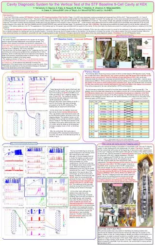
The Frascati C-band structure and the high-power test of the cavity at KEK B. Spataro (LNF-INFN, Frascati, Italy) on behalf of the SPARC/X C-Band group SLAC, XB11 17/05/2011
THANKS TO ALL CONTRIBUTORS Design: D. Alesini and V. Spizzo (Univ. of Rome “La Sapienza”) Mechanical design and Realization: D. Alesini, V. Lollo, R. Di Raddo, P. Chimenti Beam dynamics: M. Ferrario, V. Fusco, C. Vaccarezza SLED design: B. Spataro, F. Marcellini Test at KEK: D. Alesini, L. Palumbo, R. Boni, A. Gallo, S. Quaglia, F. Marcellini, A. Battisti, G. Di Pirro, R. Clementi Toshiyasu Higo, Shuji Matsumoto, K. Kakihara (KEK) Silvia Verdu Andres (CERN) Klystron, Modulator, Installation, logistics, financial support: R. Boni, G. Di Pirro, L. Palumbo
OUTLINE • Design Overview • Realization • High power RF test at KEK
SPARC PHOTO-INJECTOR RF GUN: -2.856 GHz -1.6 cell Solenoids LINAC: -S BAND -3 sections (3 m long) -Diagnostics (RF deflector) -quadrupoles matching -seeding UNDULATORS SPARC
SPARC ENERGY UPGRADE WITH C BAND SYSTEM ACC. SECTION GUN The SPARC energy will be upgraded from 170 to >240 MeV by replacing a low gradient S-band traveling wave section with two C-band units. We decided to implement this system at SPARC to explore the C Band acceleration (RF components, construction at LNF TW sections, SLED, syncronization) in hybrid scheme with S Band: -Higher gradients -Very promising from the beam dynamics point of view Klystron N°1 3 dB splitter ATT E ≈ 170 MeV 20 ÷ 22 MV/m ≈ 130 MeV ACC. SECTION ACC. SECTION PULSE COMPRESSOR ≈ 13 MV/m Klystron N°2 C-band acc. structures > 35 MV/m • The new C-band system consists mainly of: • 2 accelerating sections (1.4 m long) • 1 C-band klystron (50 MW), by Toshiba Ltd (JP) • 1 Pulsed HV modulator supplied by ScandiNova (S) • WR187 waveguide system • 400 W solid state driver supplied by MitecTelecom (CDN) • SLED E > 240 MeV 1.4 m 1.4 m ≈ 50 MW ≈ 50 MW (Half pulse) C-band Station 2.5 μs ≈ 100 MW/0.20μs 5712 MHz – 50 MW C-band ENERGY COMPRESSOR
THE C BAND STRUCTURE AND THE PROTOTYPE C BAND structure Splitter: to have a symmetric feeding system. Coupler design: based on the “new generation” of couplers proposed at SLAC for high gradient X Band structures (waveguide couplers) Single cell design: optimized to work with a SLED RF pulse (and many dicussions with V. Dolgashev during his visit in Italy) Previous the construction of the two TW sections, a prototype with a reduced number of cells, has been realized. The goals of this prototype were: -test all design and construction procedure -test the structure at high power at KEK (Japan) in the framework of a collaboration between LNF-KEK.
SINGLE CELL DESIGN The structure has been designed as TW constant impedance (cells with equal radius) in order to: -simplify the fabrication -reduce the peaksurface field when the structure is feed by a SLED pulse -reduce the unbalance between the accelerating field at the entrance and at the end of the structure, due to the combination of power dissipation along the structure and SLED pulse profile. Elliptical shape The single cell has been designed: -exploring the different TW cell parameters as a functiion of the iris aperture (a), thickness (t) and ellipticity (r1/r2). -combining the parameters with the real RF SLED pulse and calculating the maximum surface field, accelerating field,.... Elliptical shape (V. Dolgashev)
STRUCTURE FINAL PARAMETERS ( with no coupler) The dimensions of the single cell have been optimized to simultaneously obtain: -lowest peak surface electric field on the irises with the SLED input pulse; -an average accelerating field of, at least, 35 MV/m with the available power from the klystron; -the largest iris aperture for better pumping, reduced wakefields contribution and reduced filling time of the structure (related to the breakdown rate probability).
COUPLER DESIGN The design of the coupler has been divided in two parts: -the design of the waveguide coupler; -the design of the splitter. splitter Advantages: -integrated symmetric feeding -low H field pulsed heating -Better pumping waveguide coupler Disadvantage: -multipolar field components (quadrupole) The analysis of the multipolar field components have been done (see technical note (D. Alesini et al.).
REALIZATION OF CELL AND COUPLERS @ COMEB S.r.l. Cooling pipes Cells Turning machine “Shaumblain” Cell Ra<0.05m tolerances 2m Tuning by deformation Input coupler cumputer controlled milling machine Ra<0.2m tolerances 10m Output coupler: Electro discharge machining Ra<1m tolerances 20m
BRAZING @ LNF • The structure has been brazed @ LNF in several steps: • -Cells • Couplers • Final brazing • Intermediate RF measurements have been done during realization Main problem during the realization: -alignment of coupler and cells in the final brazing process
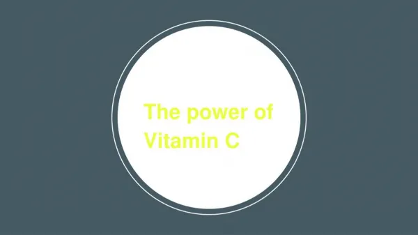
HIGH POWER TESTS AT KEK: TEST AREA (1/2) SLED Prototype
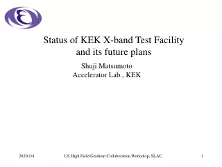
STRUCTURE CHARACTERIZATION AT HIGH POWER (2/2) PF=klystron output power See S. Verdu Andres Talk for comparison with X-Band BDR
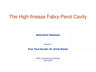
For the SLED design we investigated cavities with ellipsoid – like shape in order to increase the quality factor Qoand remove the modes degeneration. P. Fernandes, R. Parodi, C. Salvo, B. Spataro: "The Design of the TE Storage Cavities for a RF Pulse Compressor System". NIM A 288 (1990) pp. 549-554. TE037 storage cavity TE028 storage cavity Frequency 5712 MHz Qo = 135000 (unloaded) β = 6 ΔF ~ 13 MHz (min. frequency separation ) Relevant sizes : L ~ 24 cm ( cavity axial length) L/D = 1 ( with D the cavity diameter)
CONCLUSIONS FOR THE C BAND • Design: SLED oriented, large irises, low filling time • (D. Alesini, et al., SPARC note RF-11-002, 2011) • 2)Realization: LNF+ local companies • 3) Results of high power RF test at KEK: 50 MV/m with BDR<1e-6 • As responsible of the Frascati Laboratory for the technological transfer activity, we have given to the local private company (COMEB S.r.l. involved in our projects) astrong economic impact, new know – how, new permanent recruitment, new orders from other institutions ( domestic and international) and so on,in the order of the following areas: • 1)X - Band : thank you very much again to S. Tantawiand V. Dolgashevfor them help !!! ; • 2) RF deflectors designed and realized for the CERN,PSI,ELETTRA ; • 3) First PETS prototype fabricated for the CERN ; • 3) New Frascati RF gun ( fabrication in progress); • 4) Design and realization of the Frascati C band section ; • 5) Training for young scientist as : L. Faillace (Radiabeam), A. Falone( PSI), C. Vicario (PSI) and • many other ones !!!
Some words for the X-Band activities status The work of the X-Band fabricated with the EBW is made possible by the efforts : SALAF Group, INFN - LNF V. Dolgaschev,S. Tantawi , A.D. Yeremian, SLAC Y. Yigashi, KEK L. Palumbo, University of Roma 1 5th Collaboration Meeting on X-band Accelerator Structure Design and Test Program May 16h -18th, 2011- National Accelerator Laboratory Menlo Park, SLAC
Triple choke standing wave structure (A.D. Yeremian, V.A. Dolgashev, S.G. Tantawi, SLAC) http://accelconf.web.cern.ch/accelconf/IPAC10/papers/thpea065.pdf Preliminary Solid Model p mode e.m. distribution p mode field profile on axis Studies on the mechanical drawings in order to separate vacuum and RF- joint to test molybdenum and hard alloy structures are in progress, too. p mode coefficient reflection
Prototype ready to be used for the EB technique Use of the Electron Beam Welding technique EBW was used for a welding test of an X-band cavity sample. Cross section of the prototype 3 mm cavity Tool to keep together the 2 half-cavities during pre-bonding Sample pre-bonding @ 300°C EB welded sample The pre-bondingisused in ordertoprevent : 1) microgapsleftbywelding (on the cellsurface) [vacuum leakage tests gave about 10-10mbarlitre/sec] 2) accidental pocket air inclusions 3) EBW damages in the internalsurfaceof the structure 0.04 mm 0.6 mm
…… use of the Electron Beam Welding technique Macrographic inspection of EB welded joints, made on a X-band test specimen The welding meets the requirements of the applicable specification SI 01.003 revA No cracks have been found in the fusion zone and in the heat affected zone. There are only small porosities at the root-side of the weld joint which are, however, within the limits of the specs. Moreover dimensional mechanical tests before and after welding gave negligible difference. pre-bonding zone The joints in the pre-bonding region demonstrated to work well and additional tests are in progress, too. EBW zone
Macrographic inspection of EB welded joints, made on a X-band test specimen Carrried out by HTC (High Technology Center April 14 – 2011)O Specimen Identification Test Specimen (after welding process) Electron Beam Welding region. Again no cracks have been found in the fusion zone and in the heat affected zone The joints in the pre-bonding region demonstrated to work well. Vacuum leakage tests after the Welding process gave about 5 10-10 mbar litre/sec Cavity (inside)
Copper Triple choke fabrication Triple choke section mechanical drawing Triple choke section solid model Copper real triple choke cavity after Electron Beam Welding process Gasket in order to separate vacuum and RF-joint to test molybdenum and hard alloy structures
Assembling of all cells for making the pre-bonding process Single cavity Devices after the pre-bonding process ready for making the Electron Beam Welding process Prototype Real model
Bead-pull measurements of triple choke cavity made of Cu and E.B.W. process Frascati low power test data An about 40 MHz frequency increase of the p mode has been obtained after the welding process. Investigations are in progress !!!
Fields profile on axis measurements Triple choke cavity pmode Q0=8368 2p/3 mode Q0=8289 p /3 mode The baking of the triple choke cavity structure is in progress, too. Q0=7962