Download
1 / 36
390 likes | 651 Vues
CSU-CHILL Radar. October 12, 2009. Outline. Brief history Overall Architecture Radar Hardware Transmitter/timing generator Microwave hardware (Frequency chain, front-end) Antenna Digital receiver Radar Software Signal Processor The “Virtual CHILL” - VCHILL Future Plans.

E N D
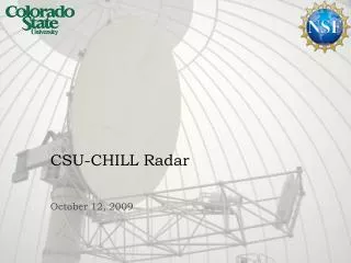
CSU-CHILL Radar October 12, 2009
Outline • Brief history • Overall Architecture • Radar Hardware • Transmitter/timing generator • Microwave hardware (Frequency chain, front-end) • Antenna • Digital receiver • Radar Software • Signal Processor • The “Virtual CHILL” - VCHILL • Future Plans
Brief History of the Radar • Constructed in 1970 at the University of Chicago and the Illinois State Water Survey • Directed by Dr. Eugene Mueller • Originally a single-polarization S-band system, derived from FPS-18 • Made a National Science Foundation facility in 1985 • Moved to Colorado State University in 1990 • Converted to a dual-polarization system with a single transmitter in 1981 • Second transmitter added in 1995 • Signal processor upgraded to “CDP” in 2005-6 • Dual-offset antenna system installed in 2008
CSU-CHILL Radar Architecture Antenna Radome Radar Trailer Signal Processor Dual Transmitters Transmit Controller Storage Processor Mass Storage Network Sync Local Display, Control Dual Receivers Digitizer, Filtering Antenna Servos Remote Display, Control Gateway Angle System Control Internet
Transmitter/timing generator • Synthesizes arbitrary, independent waveforms for CHILL’s dual transmitters • Agile FPGA-based timing generator • Used to generate a wide variety of transmitter waveforms • Intra-pulse coded • Inter-pulse phase coded • Differential coding on each polarization channel • 0.2 degree pulse-to-pulse phase setting accuracy • 50 MHz output frequency Memory Processing FPGA Digital Upconverters Transmitter and Timing Waveform generator board
Transmitter/timing generator (cont’d) • Rectangular pulse produces frequency-domain sidelobes • Increases spectral occupancy • Wider radar bandwidth makes it harder to predict radar behavior • Digitally synthesized Gaussian pulse limits spectral sidelobes Gaussian-weighted Pulse Rectangular Pulse
Transmitter/timing generator (cont’d) • Complex waveforms are also possible • Linear FM • Inter-pulse phase-coded signals • Staggered PRT • Block-staggered PRT • Unique waveforms • V-H-VH polarization • Independently phase-coded V,H channels Linear FM waveform
Microwave hardware • Convert 50 MHz IF waveform to RF, at 2725 MHz • Generate drive power for Klystron • Amplify very weak return signals at 2725 MHz • Convert received signals to IF at 50 MHz for digitization • All signals referred to GPS for time-stability GPS Ref STALO IF Filter RF Filter IPA Klystron Digital Upconverter Triggers, Clock Calibration Hardware To Antenna LNA Digital Receiver Limiter Only one channel shown…
Microwave hardware (cont’d) Existing transmit chain, has been in use at CHILL since 2006 “Needs some work”
Fast Switch Microwave hardware (cont’d) RF Filter IF Filters Mixer Updated frequency chain sub-plate Contains a single channel Rx Digital Step Attenuator Tx Digital Step Attenuator
Power Supply Microwave hardware (cont’d) Monitoring board Picture shows the frequency chain subplates assembled, with STALO, LO distribution, power supplies, monitoring subsystem Enclosure only partially complete STALO synthesizer LO distribution T/R Subplates for V, H channels
IPAs Power Supply Microwave hardware (cont’d) Initial power amplifier subsystem for Klystrons Generates up to 40W pulsed RF power Needs an enclosure Monitoring board
LNAs Microwave hardware (cont’d) Cal Switches Front End Includes LNAs, mixers, LO distribution and monitoring Includes calibration switches Mixers RF Filters
CSU-CHILL Antenna Main reflector • Dual-offset Gregorian antenna • High surface accuracy • Main: 0.012 in RMS • Sub: 0.002 in RMS • Symmetric OMT feed horn • Sidelobe levels better than 50 dB • On-axis cross-polar isolation better than 50 dB • System LDR limit of -41 dB • Median LDR in light rain of -38 dB • Will be upgraded with a dual-frequency horn Feed horn Subreflector
CSU-CHILL Antenna (cont’d) Main reflector assembly Splits apart into three pieces for transportability
CSU-CHILL Antenna (cont’d) Adding the remaining panels of the main reflector
CSU-CHILL Antenna (cont’d) Installing the feed boom
CSU-CHILL Antenna (cont’d) Attaching the main reflector and feed boom to the pedestal
CSU-CHILL Antenna (cont’d) Adding photogrammetry patches to the main and subreflectors Photogrammetry establishes the surface accuracy and alignment of the main- and sub-reflectors
CSU-CHILL Antenna (cont’d) Performing photogrammetry
CSU-CHILL Antenna (cont’d) Installing the radome, in deflated stage
CSU-CHILL Antenna (cont’d) Pulling the radome edge over the tie-down rings
CSU-CHILL Antenna (cont’d) Inflating the radome Inflation Blower
CSU-CHILL Antenna (cont’d) Radome inflation completed
Digital Receiver Digital Receiver FPGA board – ICS554. Processing FPGA performs digital down-conversion, filtering and tagging of data with time, antenna position information and transmitter polarization state. High-speed analog to digital converters Processing FPGA
Digital Receiver – IF Sampling Process • The ADCs on the digital receiver sample the 50 MHz IF at 40 MHz: sub-Nyquist sampling • This implicitly performs a downconversion from 50 MHz to 10 MHz • Anti-alias filters prevent noise at 30, 70 MHz from mixing down Digital Filter Wanted Signal Anti-alias Filter fs/2 Aliased Signal 3fs/2 fs Residual Noise Wideband Noise 0 10 20 30 40 50 60 70
Digital Receiver (cont’d) • Digital receiver filtering process is accelerated by the hardware implementation • Performs 9 billion 16-bit multiplications per second • Received data is handed off to host PC through PCI bus • Host PC serves out time-series (I/Q) data to multiple clients for further processing • Signal processor • Real-time debugging A-scope/spectrum display • Time-series archiving
Signal Processor – Architecture Digital Transmitter Archiver Node • CSU-CHILL’s signal processor uses general-purpose PC hardware to compute meteorological products from the DRS data • Software agents running on different nodes provide the functionality of the signal processor • All nodes communicate by Ethernet • Any of these nodes may be located physically distant from the radar, as long as network connectivity is available • The signal processor implementation is designed to be easily expandable Digital Modulator Transmit Control Server DRS Archive Server Disk Array IF Signals (H,V) Triggers Product Archive Server Acquisition Node Digital Receiver FPGA Acquisition Server IF Signals (H,V) Data Replay Server Triggers Signal Gen, Pwr Meters Instrumentation Server Operator’s Node System Controller Processing Node Compute Thread Product Calculation Server Radar Display Compute Thread Gateway Node Display Node External Network Gateway Radar Display Gigabit Ethernet
Signal Processor –Product Calculation Server • Covariance estimates are made using either pulse-pair processing (PPP) or spectral (FFT) processing • PPP mode uses a selectable IIR clutter filter • FFT mode uses an adaptive spectral clipper which estimates the noise floor and clutter power, then interpolates over the clipped spectral points • Variety of processing modes • Various polarization diversity modes • Indexed beam mode • Long integration mode • Phase coding mode • Block-PRF mode • Oversample-and-average mode • All modes are dynamically selectable from system controller
Signal Processor Applications –LDR from Simultaneous Mode • Linear Depolarization Ratio (LDR) is a measure of how the medium within the radar resolution volume depolarizes the transmitted signal • Resolution volume containing uniform particle distribution is characterized by low LDR, higher LDR indicates mixed precipitation • Measured in alternating transmit mode by radiating on one polarization channel, while measuring the return on the other channel • Simultaneous transmit mode normally cannot measure LDR due to co-polar return signal mixing with the weak cross-polar signal H Port Depolarizing Medium PH LDR=PV/PH PV V Port
Signal Processor Applications –LDR from Simultaneous Mode • In simultaneous mode, orthogonal inter-pulse phase codes ψh and ψv are applied to each polarization channel (indicated by color in the diagram below) • The received signals are given below (k indicates pulse sequence index) • The signals are decoded by multiplying with the conjugate of the codes ψh and ψv, giving • The codes φh=ψh-ψv and φv=ψh+ψv are chosen for their spectral characteristics, in this case, orthogonal Walsh codes are used • The Walsh code has the property of shifting the cross-polar signal (Vhv or Vvh) by π in the spectral domain, permitting recovery of both co- and cross-polar signals H Port PHV Depolarizing Medium ψv coded PHH PVV PVH ψh coded V Port LDR=PHV/PVV =PVH/PHH
Applications – LDR from Simultaneous Mode • To verify the performance of this algorithm, DRS data was collected using the radar on May 29, 2007 during a stratiform rain event containing a prominent bright-band • The radar performed RHI scans first in alternating mode to collect truth data, then in the coded simultaneous mode. They show good agreement, as shown below • The ability of CHILL to independently phase-code each channel, as well as the high phase-setting accuracy of the digital modulator provide this new capability Bright Band
Signal Processor – “Virtual CHILL” • The “Virtual CHILL” initiative involves making the radar available over the Internet to multiple locations • Real-time time-series and moments data available remotely • Remote control over all aspects of radar operation • One aspect is the “Java VCHILL” radar data browser Radar Controller/ Signal Processor/ Storage Tx. Waveform Rx. Signal Radar Hardware Internet Remote Client Remote Clients Remote Processor
Future Plans • Dual-frequency horn • Improved Zdr calibration methodology • Fully automated operation • Integration with S-Pol to form the Front-range Observational Network Testbed • Improved transmitter (TWTA/solid-state)