Download
1 / 1
30 likes | 443 Vues
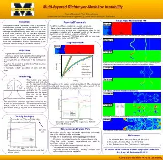
Multi-layered Richtmyer-Meshkov Instability. Pooya Movahed , Prof. Eric Johnsen Department of Mechanical Engineering, University of Michigan, Ann Arbor. Single-mode Multi-layered RMI. Numerical Framework The 2D inviscid Euler equations are solved numerically.

E N D
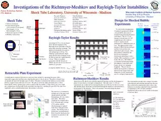
Multi-layered Richtmyer-Meshkov Instability PooyaMovahed, Prof. Eric Johnsen Department of Mechanical Engineering, University of Michigan, Ann Arbor Single-mode Multi-layered RMI • Numerical Framework • The 2D inviscid Euler equations are solved numerically. • Base scheme: second-order accurate MUSCL-Hancock. • Interface-capturing scheme: Roe’s approximate solver for the conservative variables with a ɣ-based model for the transport equation to prevent spurious pressure oscillations2. • Programming language: FORTRAN with MPI for intra-node communication (using up to 96 CPUs). Density Shock Air SF6 Air Initial conditions: A M 1.3 shock wave in air moves right toward perturbed layer of SF6. Schlieren Single-mode RMI Motivation The physics of inertial confinement fusion (ICF) combine hydrodynamics, plasma physics and radiation. One of the important hydrodynamic processes in ICF is the Richtmyer-Meshkov instability (RMI), which occurs when a shock wave interacts with an interface separating different fluids1. The RMI reduces the yield of the reaction by mixing the ablator with the fuel. Through numerical simulations of the multi-layered RMI in a shock tube configuration, a basic understanding of the role of the RMI and mixing in ICF can be achieved. Density • Objectives • The goals of the present work are to: • Develop a parallel code capable of simulating multi-component flows in a robust and accurate fashion. • Investigate the role of reshock in the multi-layered RMI, • Analyze the accuracy of available analytical solutions for the RMI at late times, and • Investigate vorticity generation at early and late times. Shock Vorticity Air SF6 Before reshock: The baroclinic vorticity has different signs along the top/bottom parts of the interface and the second interface has gone through a phase change. Schlieren Terminology The bubble and spike amplitudes ab(t) and as(t) are the distances from the shocked and unperturbed interface to the bubble and spike tips. The spikes penetrate into the lighter fluid and roll up while bubbles rise into the heavier fluid. Vorticity Comparison of the present numerical results with different analytical models and experiments by Jacobs. Normalized growth of the amplitude as a function of normalized time. After reshock: Mushroom shape structures develop. Schlieren The mixing layer amplitude a(t) is the average of the bubble and spike amplitudes. The dimenisionless time is Ƭ=kv0t, where k is the wave number of the initial perturbation and v0 is the post-shock Richtmyer velocity. Vorticity Vorticity Evolution Long time after reshock: secondary baroclinic vorticity is produced3. Density Circulation versus time for the single-mode RMI with reshock(t=1.8msec). • Conclusions and Future Work • Baroclinic vorticity: basic mechanism determining the growth rate of the bubble and spike amplitudes. • Sharp rise in circulation just after the passage of the shock • - Circulation increases afterwards due to secondary vorticity. • The flow exhibits turbulent characteristics and leads to significant mixing at late times. • To capture the detailed turbulent mixing at late time: • Diffusive terms must be included, • High-order accurate schemes (e.g., WENO) should be used to minimize the numerical dissipation. Baroclinic term Very late time: mixing and turbulence regions develop. References M. Brouillette, Annu. Rev. Fluid Mech. 34, 445 (2002). R. Abgrall, J. Comput. Phys. 125, 150 (1996). N. J. Zabusky, Annu. Rev. Fluid Mech. 31, 495 (1999). 1st Annual MPISE Graduate Student Symposium Conference Ann Arbor, MI, September 29, 2010 Circulation versus time for the single-mode RMI without resock Computational Flow Physics Laboratory