Download
1 / 49
490 likes | 633 Vues
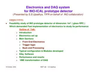
Electronics and DAQ system for INO-ICAL prototype detector ( Presented by S.S.Upadhya, TIFR on behalf of INO collaboration). OBJECTIVE: Feasibility study of INO prototype detector of dimension 1m 3 ( glass RPC ) Which demanded Fast implementation of electronics to study its performance

E N D
Electronics and DAQ system for INO-ICAL prototype detector(Presented by S.S.Upadhya, TIFR on behalf of INO collaboration) OBJECTIVE: • Feasibility study of INO prototype detector of dimension 1m3 ( glass RPC ) Which demanded Fast implementation of electronics to study its performance Outline of Talk: • Introduction • Electronics set up • Main Sections • Front End Electronics • Trigger logic • Back end Processing • Typical configuration & Modules developed • DAq. Software • Performance and results • VME transformation of DAQ ASET talk - S.S.Upadhya
Introduction to Glass Resistive Plate Chamber (RPC) • Glass RPC is a gaseous detector- gas mixture flown at the atmospheric pressure -Electric field is applied across the glass electrodes. • An ionizing charged particle traversing the gap initiates a streamer in the gas volume that results in a local discharge( limited to 0.1cm2) of the electrodes. • The discharge induces an electrical signal on external pickup strips on both sides, orthogonal to each other, which can be used to record the location and time of ionization. • The RPC can be operated in either in streamer mode or avalanche mode. Typical signal amplitude is about 100-200mV in streamer mode where as few mV in avalanche mode and its rise time is less than a nano Second. • Signal is derived from a pick strip and common ground plane onto a twisted pair line of 100 ohm impedance. ASET talk - S.S.Upadhya
Construction of RPC Two 2 mm thick float Glass Separated by 2 mm spacer 2 mm thick spacer Pickup strips 30mm Glass plates 2 mm Gas chamber Resistive coating on the outer surfaces of glass ASET talk - S.S.Upadhya 3
CAMAC back end DETECTOR RTC Final Trigger INO controller TDC Readout Mod. Monitor Scaler CAMAC Controller RPC 60mm iron Z=1m Front end Electronics Y=1m X=1m Prototype Detector and Electronics • Detector Specifications: • 12 layers of RPCs • RPC has X & Y-planes (orthogonal strips) • Each plane gives 32 pick up signals • Total no. of channels = 12x2x32 • = 768 • Informations to be recorded on every valid trigger : (Few per min) • Event time up to micro secs (RTC) • Particle interaction tracks (boolean status of X-Y pick-up signal in each layer) 768 bits • relative time of interaction along the layers(X-Y planes) of RPCs (24 TDCstops) • Design Considerations: • Flexibility and scalability • Fast implementation using available resources and expertise • Custom design standard at front end and CAMAC standard at back end with a serial transfer of data ASET talk - S.S.Upadhya
Electronics Set up Front End Layer 1 (X) [EveID,MonID] Layer 1 (Y) SIGNAL ROUTERS Trigger & TDC Control – Data Monitoring Amplifier and Discriminator Processing and Monitoring Processing and Monitoring Amplifier and Discriminator Layer 12 (Y) Layer 12 (X) Processing and Monitoring Amplifier and Discriminator Amplifier and Discriminator Processing and Monitoring Back End Mon Scalers Eve Scalers RTC TDC Read out Controller TRIGGER CAMAC Controller CAMAC system • User configurable Daisy chain : an interface between Front end and Back end electronics for control, data transfer and monitoring • Event daisy chain : 1 each for X & Y planes of 12 layers [T,E/-M,Ad(4),SD,Clk] • Monitor daisy chain: 12 no.s ( 1each for 2 consecutive layers in X & Y planes )[M,R,Clk] • Note: MAX length of a daisy chain can be 16 modules due to 4 bit address ASET talk - S.S.Upadhya
Main Sections of Electronics • Front End Electronics • Amplifier & Discriminator • Processing and Monitoring • Signal Routers • Trigger logic • Front end (Tigger-0 & 1) • Back end (Final Trigger) • Back end Processing • Event process • Monitor process ASET talk - S.S.Upadhya
Front end: Amplifier & Discriminators • 8 channel Amplifier : • RPCs in avalanche mode gives very small • pulses of few mV and hence signal is amplified • Specifications : • placed close to pick-up strips • a gain of 80 • rise time of 2 ns • Front End Discriminator: • Converts the pickup signals over set • threshold to digital signals (Diff ECL) • Specifications: • 16 channels per module • common threshold variable from 2 to 500mV • houses Trigger-0 logic also 1595+1513 1597+1513 AD96687 ASET talk - S.S.Upadhya
Amplifier output ASET talk - S.S.Upadhya
Front End: Processing & Monitoring Discriminator signals ( 32 Diff. ECL ) T0 signals from Discriminator Translator and wave shaper (TTL & 400ns width) M fold coincidence (Trigger-1 logic ) CPLD Board ID [8 bit] T1 signals 48_bit Parallel to Bit Serial Event Register clk SO SI load 2:1 MUX • 0ne per plane of RPC • Registering track data and transfer serially • Select a pick up signal for monitoring Eve SO 2:1 MUX Mon SO Eve SI Mon SI 40:1 MUX T EveClk EveEn Cal Freqs Eve & Mon Decoder Mon ID MonEn MR 6_bit Counter (Mon Chnl Addr) Eve ID MClk CPLD Translator (LVDS to TTL) Translator (TTL to LVDS) • INTERFACE SIGNALS • EveCom (event daisy chain) • OUT : EveSO, EveClk, Addr(4), E/ nM ,T • IN : EveSI, EveClk, Addr(4), E/ nM ,T • Mon :: (Monitor daisy chain) • OUT : MonSO , MClk, MR • IN : MonSI , MClk, MR EveCom Mon Interface signals EveCom Mon Interface signals ASET talk - S.S.Upadhya
EVENT READ OUT CYCLE: Board 0 ADDR(4) Board 1 E / M Clk SO Monitor cycle E/ M ADDR(4) Board 0 MR Mclk MO First pulse after address enables the board for monitor Next channel selection Sequence of Signals in Event and Monitoring process ASET talk - S.S.Upadhya
Captured Event data transfer of Layer 0 Bd ID ASET talk - S.S.Upadhya
Captured event data transfer of layer 11 ASET talk - S.S.Upadhya
Processing & Monitoring module XC 9536 Trigger-1 Event (48 bit)=BdID(6)+F(4)+MCh(6)+Pickup(32) • Processing and Monitoring module: • Latches Boolean status of 32 pick up signals and board ID, on a final trigger • Transfers latched data over event daisy chain • Select the channels for monitoring • Generates M fold trigger –T1 per plane • Board has board-ID, event-ID, monitoring-ID • one per plane ie total of 24 modules XC 95288 Processing & Monitoring ASET talk - S.S.Upadhya
Front End:: Signal Routers • Routing of like signals between Front end and Back end • Trigger & TDC Router: • Routes primitive Trigger signals and TDC stop signals from each front end Processing boards of RPC planes to Final TRIGGER module and TDC module at back end CAMAC • Control & Data Router: • Caters the control signals from INO controller at back end to all the front end Processor modules via daisy chains • Routes serial event data and selected pick signals for monitoring from front end boards via respective daisy chains to Read out board and Monitor Scalers at back end. ASET talk - S.S.Upadhya
Trigger Logic (MxN fold) For X-planes • in Front End Discriminator (FED) module[ TRIGGER 0 LOGIC - T0 trigger] • Pickup signals crossing set threshold converted to DIGITAL (diff ECL) ; typical rate ~200Hz • Every 8th pickup signals in a plane are logically ORed to get T0 signals (S0 to S7) Sn rate is 4x200= 800Hz • In Processing and Monitoring module[ TRIGGER 1 LOGIC - T1 trigger] • M fold coincidence of S1 to S8 signals (equivalent to M fold coincidence of consecutive pickup signals in a plane)- 1F,2F,3F,4F • Final Trigger Module ( CAMAC std. )[ TRIGGER 2 LOGIC - T2 trigger ] • M fold signals(1F,2F,3F,4F) from all the X-planes are the inputs (diff LVDS) • MxN fold trigger is generated ie N fold coincidence of M fold (T1) triggers from consecutive planes typical MxN folds implemented are 1x5, 2x4, 3x3, 4x2 For Y-planes • Similarly MxN fold for Y-plane is generated Final Trigger is logical OR of MxN fold trigger from X and Y-planes • Final Trigger invokes DAq system via LAM to record the event information. • Eg: M = 1F :: S0+S1+….+S7 • M = 2F :: S0.S1+S1.S2 + S2.S3 + S3.S4 + ….. + S7.S0 • M = 3F :: S0.S1.S2+S1.S2.S3 + S2.S3.S4 + S3.S4.S5 + ….. + S7.S0.S1 • M = 4F :: S0.S1.S2.S3+S1.S2.S3.S4 + S2.S3.S4.S5 + ….. + S7.S0.S1.S2 BACK ASET talk - S.S.Upadhya
Final Trigger Module • Final Trigger Module: • M folds of all X & Y planes are inputs • Generates MxN folds - final trigger • Final trigger invokes LAM • Inputs and MxN outputs of trigger logic are individually mask-able. • Counting of all triggers by built-in scalers • Boolean status of M fold signals are latched on final trigger for later reading • design is FPGA based ASET talk - S.S.Upadhya
Event Process Monitor Process Final Trigger Periodic 1Hz Trigger from INO controller Registers Track data in front end Event time,TDC data and Trigger rates at back end Register the counting rate of selected pick-up signal in Mon-Scaler Invokes LAM for Event process SW via INO controller initiates track data transfer serially to Read-out module Registered Data is ready for reading into PC via CAMAC bus Registered Data is ready for reading into PC via CAMAC bus Back end Processing:: Event and Monitor process ASET talk - S.S.Upadhya
E/M Mon LAM 10MHz MClk % n Mon MR MO SW INO Controller Event process SW 10MHz SO Test Pattern(8) % n Event Clk T Event Bit counter Eve Com Module Address Counter(4) %48 Monitor process ASET talk - S.S.Upadhya
INO Controller • INO Controller: • In Event process, SW initiates the Controller to flush data serially from all processing modules over event daisy chains. • In Monitoring process, It selects the channels to be monitored. • Event and monitoring parameters like event data transfer speed, data size, monitoring period etc. are user programmable via CAMAC interface • SW controlled Diagnostic features for DAq. is supported. ASET talk - S.S.Upadhya
Fig.6 INO Controller INO Controller ASET talk - S.S.Upadhya
EveCom and Mon interface signals EveClk EveClk Event Event Mon MO (1 to 8) EveSO EveSO Serial In Parallel Out Shift REG(16) clk Serial In Parallel Out Shift REG(16) clk Translator LVDS to diff ECL W W FIFO Buffer(16) FIFO Buffer(16) OF To Monitor Scalers OF CAMAC Function & Address Decoder CAMAC bus INO Readout Module ASET talk - S.S.Upadhya
INO Readout Module • Read-out Module: • Receives Event data over 2 serial connections and 8 pick-up signals for monitoring from 8 monitor daisy chains. • Serial Data converted into 16bit parallel data and stored temporarily in FIFOs buffer. • program reads FIFO data via CAMAC interface • 8 pickup signals are converted from LVDS to ECL for Scaler compaibility ASET talk - S.S.Upadhya
CAMAC bus CAMAC bus EveCom EveCom EveCom EveCom EveCom EveCom EveCom EveCom Mon Mon Mon Mon Mon Mon Mon Mon INO Controller INO Controller INO Readout Module INO Readout Module Monitor Scaler Monitor Scaler 16 Chnl DISC 16 Chnl DISC 16 Chnl DISC 16 Chnl DISC 16 Chnl DISC 16 Chnl DISC 16 Chnl DISC 16 Chnl DISC FTO FTO 32 Chnl FEP 32 Chnl FEP 32 Chnl FEP 32 Chnl FEP 32 Chnl FEP 32 Chnl FEP 32 Chnl FEP 32 Chnl FEP EveCom EveCom EveCom EveCom EveCom EveCom EveCom EveCom Mon Mon Mon Mon Mon Mon Mon Mon Chain 1 Chain 1 X plane X plane Y plane (** Connections CDR & TTR are similar to X plane) Y plane (** Connections CDR & TTR are similar to X plane) 16 Chnl DISC 16 Chnl DISC 16 Chnl DISC 16 Chnl DISC 16 Chnl DISC 16 Chnl DISC 16 Chnl DISC 16 Chnl DISC 16 Chnl DISC 16 Chnl DISC 16 Chnl DISC 16 Chnl DISC 16 Chnl DISC 16 Chnl DISC 16 Chnl DISC 16 Chnl DISC Chain 1 Chain 1 EveCom EveCom EveCom EveCom EveCom EveCom EveCom EveCom Mon Mon Mon Mon Mon Mon Mon Mon 32 Chnl FEP 32 Chnl FEP 32 Chnl FEP 32 Chnl FEP 32 Chnl FEP 32 Chnl FEP 32 Chnl FEP 32 Chnl FEP Layer 1 signals Layer 1 signals Layer 1 signals Layer 1 signals 16 Chnl DISC 16 Chnl DISC 16 Chnl DISC 16 Chnl DISC 16 Chnl DISC 16 Chnl DISC 16 Chnl DISC 16 Chnl DISC EveCom EveCom EveCom EveCom EveCom EveCom EveCom EveCom Mon Mon Mon Mon Mon Mon Mon Mon Control and Data Router (CDR) Control and Data Router (CDR) Layer 2 signals Layer 2 signals Layer 2 signals Layer 2 signals Layer 3 signals Layer 3 signals Layer 3 signals Layer 3 signals Layer 4 signals Layer 4 signals Layer 4 signals Layer 4 signals Trigger and TDC Router (TTR) Trigger and TDC Router (TTR) • Chain 2 • Chain 2 Layer 5 to 8 Layer 5 to 8 • Chain 2 • Chain 2 Layer 5 to 8 Layer 5 to 8 • Chain 3 • Chain 3 • Chain 3 • Chain 3 Layer 9 to 12 Layer 9 to 12 Layer 9 to 12 Layer 9 to 12 FTO FTO CAMAC Controller CAMAC Controller Final Trigger Module Final Trigger Module TDC TDC RTC RTC CAMAC bus CAMAC bus Typical configuration of Electronics Setup and DAq. System ASET talk - S.S.Upadhya
Processing & Monitoing(48) Eve-Mon :: 00-00 Processing & Monitoing(48) Eve-Mon ::00-03 Processing & Monitoing(48) Eve-Mon :: 00-01 Processing & Monitoing(48) Eve-Mon ::00-02 Processing & Monitoing (48) Eve-Mon :: 01-01 Processing & Monitoing (48) Eve-Mon :: 01-06 Processing & Monitoing (48) Eve-Mon :: 01-07 Processing & Monitoing (48) Eve-Mon :: 01-05 Processing & Monitoing (48) Eve-Mon :: 02-03 Processing & Monitoing (48) Eve-Mon :: 02-02 Processing & Monitoing (48) Eve-Mon :: 02-00 Processing & Monitoing (48) Eve-Mon :: 02-01 Processing & Monitoing (48) Eve-Mon :: 10-03 Processing & Monitoing (48) Eve-Mon :: 10-02 Processing & Monitoing (48) Eve-Mon :: 10-01 Processing & Monitoing (48) Eve-Mon :: 10-00 Processing & Monitoing (48) Eve-Mon :: 11-01 Processing & Monitoing (48) Eve-Mon :: 11-06 Processing & Monitoing (48) Eve-Mon :: 11-07 Processing & Monitoing(48) Eve-Mon :: 11-05 Scalability on demand (Eg. 1m to 4m RPC) X-plane Event chain Event chain Mon chain Mon chain Event chain ASET talk - S.S.Upadhya
Event data transfer for all 12 layers ASET talk - S.S.Upadhya
DAq. Software • DAq. Program has been developed in C under Linux • Main program displays Event data, Monitor Data as well it responds to user Key hit services • EVENT RECORDING • On a Event process, program records • Event time up to microsecond • 24 TDC readings • Boolean status of all pickup signals • Useful Trigger rates • MONITORING • On a periodic Monitoring trigger ( 1Hz) • Monitor time recorded up to microsecond • Rates of selected set of channels are recorded • Next set of channels are selected for monitoring ASET talk - S.S.Upadhya
LAM Handler Main program Read LAM Register SW & HW initialization Enable LAM Handler N Event Flag Display Event and Monitor Data Program control On LAM Y . Initiate data transfer from front end to Read-out module . Record RTC time, TDC, Event Scaler . Record Read-out module data . Write data to file Any Key N Y Key Hit Services Monitor Flag N Execute Services Y . Record RTC time . Record Monitor scalers . Select next set of channels . Clear Monitor scalers Quit N Y STOP RETURN DAq. Software BACK ASET talk - S.S.Upadhya
RPC X plane RPC X plane RPC X plane RPC Y plane RPC Y plane RPC Y plane Home made Modules population in the setup INO READOUT INO CONTROLLER T&T ROUTER C&D ROUTER TRIGGER TOTAL=173 modules 12 12 24 24 48 48 ASET talk - S.S.Upadhya
Electronics and DAq. System RPC Detector Back end Electronics Front End Electronics BACK ASET talk - S.S.Upadhya
Some interesting cosmic ray tracks ASET talk - S.S.Upadhya 35
Discriminator performance – RPC pulse profile ASET talk - S.S.Upadhya
Histogram of Noise rate of pickup Chnl, Cal & Fold ASET talk - S.S.Upadhya
Avg Noise rate Monitor plot over days ASET talk - S.S.Upadhya
Histogram of Avg Noise rate over days ASET talk - S.S.Upadhya
Typical TDC distribution of a pickup plane ASET talk - S.S.Upadhya
Width matches with pick-up strip width of 28mm ASET talk - S.S.Upadhya
Change over of back end Electronics ( CAMAC to VME ) • NECESSITY TO CHANGEOVER: • Demerits of CAMAC: • Low bus speed of 3MBps as well as large deadtime leading to few Hz trigger rate capability • Limitations of scalability to large number of channels and synchronous bus cycles • As a road map to support millions of channels of information in upcoming INO-ICAL experiment, it has been decided to convert Back-end to VME based DAQ. • Building of VME Hardware expertise in house • Picked up commercial modules wherever possible • Development of customized modules equivalent to the in-house developed modules in CAMAC system, using VME based general purpose FPGA modules • Development of user friendly DAQ programs and Analysis tools to groom Software expertise to with stand SW challenges ahead in the INO experiment ASET talk - S.S.Upadhya
Introduction to VME (VERSA-Module Eurocard) ASET talk - S.S.Upadhya
VME BASED DAQ SETUP X strip signals Analog Front End Digital Front End Trigger Module Y strip signals RPC Stack Timing info Event Trigger Event/ Monitor Data VME CRATE Final Trigger Controller & Readout Module TDC Scaler Linux based DAQ software (C++, Qt, ROOT) • Interrupt Based • Multi-Threaded • Graphical User Interface • Online 2D/3D Event Display • RPC Strip Monitoring • Online Error Reporting ASET talk - S.S.Upadhya
VME at a glance power supply VME master VME slaves VME crate (chassis) • Scaler • TDC • Latch • Front End Controller & Readout • Trigger generator backplane smart fan units ASET talk - S.S.Upadhya
The standards: summary ASET talk - S.S.Upadhya
INO team at RPC lab Thank you ASET talk - S.S.Upadhya 51