Download
1 / 2
20 likes | 55 Vues
Visit https://www.huyett.com/knowledgevault/catalogs-resources for more information.

E N D
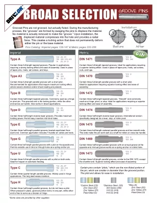
* Broad Selection Groove Pins installation Grooved Pins are not grooved, but actually fluted. During the manufacturing process, the “grooves” are formed by swaging the pins to displace the material. No material is actually removed to make the “groove.” Upon installation, the displaced material compresses into the hole and provides a radial force. This creates a locking action that does not permanently deform either the pin or the base material. Pins Catalog: Imperial pages 128-147 & Metric pages 222-256 Before After imperial Metric *CS: ZC, ZY, *SS: 300, 316, 416 *A: ZC, ZY, O *CS: O *SS: 300 Type A DIN 1471 Contain three full-length tapered grooves. Popular in applications requiring a strong locking effect and ease of assembly. Used in place of taper pins, rivets, set screws, and keys. Contain three full-length tapered grooves. Ideal for applications requiring a superior locking effect. Used in place of taper pins, rivets, set screws, nuts, and lugs. *CS: ZC *SS: 300, *A: *CS: O *SS: Type A3 DIN 1470 ZC, O Contain three full-length parallel grooves with a short pilot. Recommended for applications that require maximum locking effect, where severe vibration and/or shock loading are present. Contain three full-length parallel grooves with a short pilot. Ideal for applications requiring superior locking effect and ease of assembly. *CS: ZC *SS: 300 *A: *CS: O *SS: Type B DIN 1472 O Contain three half-length tapered grooves. Commonly used as a hinge or pivot pin. The grooved end is the locking portion, while the other end serves as handle. Also works in dowel applications. Contain three half-length tapered grooves. “Smooth” end commonly used as a hinge, pivot, or stop. Ideal for applications requiring a superior locking effect and ease of assembly. *CS: ZC *SS: 300 *A: *CS: O *SS: Type D DIN 1474 Contain three half-length reverse taper grooves. Provides maximum holding power. Permit easy insertion into blind holes. Contain three half-length reverse taper grooves. International version specifically designed as a lever, stop, or roller pivot. *CS: ZC, ZY *SS: 300, 316 *A: ZC, ZY, O *CS: O *SS: Type E DIN 1475 Contain three half-length parallel grooves located equidistant from each end. Common application includes T-handle on valves and tools. Contain three half-length centered parallel grooves and two smooth ends. The ends make the pin work well as a shaft for rollers or cross bar handle. *CS: ZC *SS: *A: *CS: O *SS: 300 Type G DIN 1469 Contain three half-length parallel grooves with an annual groove at the opposite end. Annual groove works as a spring anchor in a blind hole. Contain three half-length parallel grooves with a pilot on the opposite end. Permits versatile use in blind or through holes as a spring anchor pin. *CS: ZC, ZY *SS: 300 *A: O *CS: O *SS: Type U DIN 1473 Contain three full-length parallel grooves with a pilot on both ends. Ideal for hopper or automatic feeding. Contain three full-length parallel grooves, similar to the DIN 1470, except the chamfer end. Superior locking effect and ease of assembly. *CS: ZC, ZY *SS: 300, 316 *A: ZC, O Type C Certain pins contain “pilots,” which are the non-fluted portion of the pin, which are smaller in diameter than the grooved portion. The pilot end allows for ease in installation. Contain three quarter-length parallel grooves. Widely used in hinge applications. The long lead eases insertion. *CS: ZC *SS: 300 *A: Type H O *Alloy (A) Zinc Clear (ZC) Zinc Yellow (ZY) Plain/Oiled (O) *Carbon Steel (CS) Zinc Clear (ZC) Zinc Yellow (ZY) Plain/Oiled (O) *Stainless Steel (SS) 300 Series (300) 316 SS (316) 416 SS (416) Contain three half-length parallel grooves, but do not have a pilot. When pressed in place, grooved portion locks in one part, while other end is free to serve as a locater or hinge. *Some sizes are provided by other suppliers
Broad Selection * Groove Pins Other common references for groove pins. T echnical Drawing T ype Alt. T ype Drive-Lok Ansi A Type A Type 1 A ANSI – A B L A Type A3 Type 3 A3 ANSI – C (not a Driv-Lok C) B L A Type B Type 2 B ANSI – B C B L A Type D Type 4 D ANSI – O C B L A Type E Type 5 E ANSI – E C B L C A Type G Type 67 G ANSI – G G B L A Type U Type 3H U ANSI – F L B A Type C Type 24 C n/a C B L A Type H Type 2A H ANSI – H C B L *Some sizes are provided by other suppliers