Understanding Basic Blueprint Concepts
Understanding Basic Blueprint Concepts. ESL Resource for Aerospace Pre-Employment: AIR UNIT 1 Brian Briggs Community Colleges of Spokane. Press Space Bar to continue. What will I learn in this lesson?. The definition of a blueprint Important vocabulary and pronunciation


Understanding Basic Blueprint Concepts
E N D
Presentation Transcript
Understanding Basic Blueprint Concepts ESL Resource for Aerospace Pre-Employment: AIR UNIT 1 Brian Briggs Community Colleges of Spokane Press Space Bar to continue
What will I learn in this lesson? • The definition of a blueprint • Important vocabulary and pronunciation • The difference between CAD and CAM • Common parts of a blueprint • Basics of measurement: parts of an inch
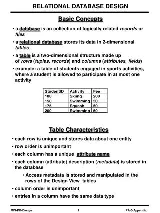
What is a blueprint? • A blueprint is a plan or design which describes how a product should be made. It shows the measurements, dimensions, and materials. In the past, blueprints were drawn by hand on special blue paper. Today, many blueprints are made on a computer using a special program called CAD (Computer Aided Drafting)
Reading Blueprints • To read a blueprint, it is important to understand the special vocabulary. You must be able to speak the language of blueprints. It is a universal language.
Important words to know-- • Line \ˈlīn\ • Dimension \də-ˈmen(t)-shən\ • Section \ˈsek-shən\ • Process \ˈprä-ˌses\ • Geometric positioning \ˌjē-ə-ˈme-trikpə-ˈzi-shəniŋ\ • Note \ˈnōt\ • Tolerance \ˈtä-lə-rən(t)s\ • Material \mə-ˈtir-ē-əl\
Dimensions give the size and location of parts and shapes. • How big are the parts? • Where do the parts go?
Sections show how the object looks inside if it were cut apart.
Geometric positioning shows exactly how far apart objects should be.
Tolerances show exact measurement and dimensions of finished surfaces.
Materials are used for making parts. The blueprint also includes information about the weight, strength, and hardness. Some common materials are iron, steel, aluminum, carbon fiber, fiberglass, titanium, and rubber.
CAD • Computer-Aided Drafting (CAD) is a computer program which helps you draft or draw blueprints on a computer.
CAM • CAM stands for Computer-Aided Manufacturing.
Things you will see on most drawings: • Name of the part • Quantity (how many are needed) • Drawing number • Dimensional tolerance • Material
Measurement • Linear or straight line measurement Measured point Reference point Line of measurement 7.5 Basic size=
Inch units • Drawings might use either inch units, metric units, or both! • Fractional parts of an inch 1/64”, 1/32”, 1/16”, 1/8”, 1/4”, 1/2” • Decimal (mils) parts of an inch .010”, .050”, .100”, and .500”
Metrics • Metric dimensions are usually given in millimeters. If you need to change measurements from one system to another, please use a conversion table.
Review • Go to the quiz and see if you understand the information. Unless otherwise specified, this work by Air Washington is licensed under a Creative Commons Attribution 3.0 United States License.