A3: Application-Aware Acceleration for Wireless Data Networks
940 likes | 959 Vues
A3: Application-Aware Acceleration for Wireless Data Networks. Zhenyun Zhuang and Tae-Young Chang GNAN Research Group, Georgia Tech, Atlanta, GA Raghupathy Sivakumar and Aravind Velayutham Asankya Networks, Inc., Atlanta, GA. Typical Application Behaviors. Thin Session Control Messages

A3: Application-Aware Acceleration for Wireless Data Networks
E N D
Presentation Transcript
A3: Application-Aware Acceleration for Wireless Data Networks Zhenyun Zhuang and Tae-Young Chang GNAN Research Group, Georgia Tech, Atlanta, GA Raghupathy Sivakumar and Aravind Velayutham Asankya Networks, Inc., Atlanta, GA
Typical Application Behaviors • Thin Session Control Messages • Sent before DATA; Small • Retransmission timer expires to recover loss • Batched Data Fetch • Data transfer is performed in batches • Bandwidth delay product cannot be fully utilized • Flow Control Bottlenecked Operations • When applications are slow, receive buffer fills up • Flow control can kick in and be the bottleneck • Non-prioritization of Data • Data are given equal importance • Non-use of Data-reduction Techniques • Application-specific and user-specific information
A3: Application-Aware Acceleration • Application aware • Recognize applications • Application transparent • No modifications to applications • A set of design elements • Transaction Prediction (TP) • Predict and issue future requests • Redundant and Aggressive Retransmissions (RAR) • Aggressively retransmit control messages • Prioritized Fetching (PF) • Divide data into different priorities and fetch them with different speed • Infinite Buffering (IB) • Use local storage to store data at the receiver • Application-aware Encoding (AE) • Compress data using application/user specific information
Transaction Prediction Deterministically predict future requests Issue them ahead of time Designed for protocols that divide data into blocks Examples, CIFS, HTTP A3: Transaction Prediction (TP)
Helps protect thin session control messages from losses Packet-level redundancy Aggressive retransmission Not applying to DATA Loss recovery is masked by subsequent packets High overhead Redundant and Aggressive Retransmission (RAR)
Divide data into categories of different priorities Fetch them with different speeds Helps protocols that treat data with equal importance Example, HTTP Prioritized Fetching (PF)
Prevents flow control from throttling the transmissions Uses local storage to store data at the receiver Flow control never kicks in Infinite Buffering (IB)
Application-aware Encoding (AE) • Uses application and user specific information • Better compress data • Example, SMTP
Other Application-Aware Networking Technologies • Cisco AON-enabled routes • Catalyst 6500/2600/2800/3800 series AON modules • Process packet according to application • Microsoft iControl • Networks inform applications about availability • Applications instruct network where to direct traffic • AT&T Application-Aware Networking (AAN) • AAN hosting and VPN markets
Outline • Introduction • Frequency reuse • Channel assignment strategies • Techniques to increase capacity • Handoff
Mobile phone subscribers worldwide 1600 1400 1200 GSM total 1000 TDMA total CDMA total Subscribers [million] PDC total 800 Analogue total W-CDMA 600 Total wireless Prediction (1998) 400 200 0 1996 1997 1998 1999 2000 2001 2002 2003 2004 year
Base Station FVC RVC FCC RCC Forward voice channel Reverse voice channel Forward control channel Reverse control channel
Cellular Concept • Challenge: limited spectrum allocation (government regulation) • A single high-powered transmitter • good coverage • interference: impossible to reuse the same frequency • Example: • One tower system in New York City in 1970 • Maximum 12 simultaneous calls/1000 square miles
Cellular Concept • developed by Bell Labs 1960’s-70’s • areas divided into cells • a system approach, no major technological changes • a few hundred meters in some cities, 10s km at country side • each served by base station with lower power transmitter • each gets portion of total number of channels • neighboring cells assigned different groups of channels, interference minimized
Cell Shape • Factors • Equal area • Non overlap between cells • Choices A3 A2 A1
For a given S • A3 > A1 • A3 > A2 • A3 provides maximum coverage area for a given value of S • By using hexagon geometry, the fewest number of cells covers a given geographic region • Actual cellular footprint is determined by the contour of a given transmitting antenna
Cellular Network Architecture Public Telephone network and Internet Mobile Switching Center Mobile Switching Center Wired network
Cellular Network Architecture • Cell • Covers geographic region • Base station (BS): analogous to 802.11 AP • Mobile users attach to network through BS • Air interface: physical and link layer protocol between mobile and BS • MSC • Connects cells to wide area network • Manages call setup • Handles mobility
Ingredients 1: Mobile Phones, PDAs & Co. The visible but smallest part of the network!
Ingredients 2: Antennas Still visible – cause many discussions…
Ingredients 3: Infrastructure 1 Base Stations Cabling Microwave links
Ingredients 3: Infrastructure 2 Not “visible“, but comprise the major part of the network (also from an investment point of view…) Management Data bases Switching units Monitoring
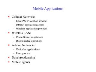
Cellular networks: the first hop • Two techniques for sharing mobile-to-BS radio spectrum • combined FDMA/TDMA: • divide spectrum in frequency channels • divide each channel into time slots • CDMA: • code division multiple access
Frequency Reuse • Adjacent cells assigned different frequencies to avoid interference or crosstalk • Objective is to reuse frequency in nearby cells • 10 to 50 frequencies assigned to each cell • transmission power controlled to limit power at that frequency escaping to adjacent cells • the issue is to determine how many cells must intervene between two cells using the same frequency
Frequency Reuse • each cell allocated a group k channels • a cluster has N cells with unique and disjoint channel • groups, N typically 4, 7, 12 • total number of duplex channels S = kN
System Capacity • Cluster repeated M times in a system • Total number of channels that can be used (capacity) • C = MkN = MS
Cell Size: Tradeoff • Smaller cells higher M higher C + Channel reuse higher capacity + Lower power requirements for mobiles • Additional base stations required • More frequent handoffs • Greater chance of ‘hot spots’
Effect of cluster size N • channels unique in same cluster, repeated over clusters • keep cell size same • large N : weaker interference, but lower capacity • small N: higher capacity, more interference need to maintain certain S/I level • frequency reuse factor: 1/N • each cell within a cluster assigned 1/N of the total available channels
Design of cluster size • In order to connect without gaps between adjacent cells (to Tessellate) • N = i2 + ij + j2 where i and j are non-negative integers • Example i = 2, j = 1 • N = 22 + 2(1) + 12 = 4 + 2 + 1 = 7
Nearest Co-channel Neighbor • move i cells along any chain or hexagon. • then turn 60 degrees counterclockwise and move j cells. N=19 (i=3, j=2) A
Channel Assignment Strategies: Fixed Channel Assignments • Each cell is allocated a predetermined set of voice channels. • If all the channels in that cell are occupied, the call is blocked, and the subscriber does not receive service. • Variation includes a borrowing strategy: a cell is allowed to borrow channels from a neighboring cell if all its own channels are occupied. This is supervised by the MSC.
Channel Assignment Strategies: Dynamic Channel Assignments • Voice channels are not allocated to different cells permanently. • Each time a call request is made, the serving base station requests a channel from the MSC. • The switch then allocates a channel to the requested call based on a decision algorithm taking into account different factors: frequency re-use of candidate channel and cost factors. • Dynamic channel assignment is more complex (real time), but reduces likelihood of blocking.
Interference and System Capacity • major limiting factor in performance of cellular radio systems • sources of interference: • other mobiles in same cell • a call in progress in a neighboring cell • other base stations operating in the same frequency band • Non-cellular system leaking energy into the cellular frequency band • effect of interference: • voice channel: cross talk • control channel: missed or blocked calls • two main types: • co-channel interference • adjacent channel interference
Co-Channel Interference • cells that use the same set of frequencies are called co-channel cells. • Interference between the cells is called co-channel interference. • Co-channel reuse ratio: Q = D/R • R: radius of cell • D: distance between nearest co-channel cells • Small Q small cluster size N large capacity • large Q good transmission quality • tradeoff must be made in actual cellular design
Worst Case Interference • When the mobile is at the cell boundary (point A), it experiences worst case co-channel interference on the forward channel. • The marked distances between the mobile and different co-channel cells are based on approximations made for easy analysis.
Worst Case Interference • S/I ~ R-4 /[2(D-R)-4 + 2(D+R)-4 + 2D-4] D+R D D+R D-R D D-R
Adjacent Channel Interference • Interference resulting from signals where are adjacent in frequency to the desired signal. • Due to imperfect receiver filters that allow nearby frequencies to leak into pass band. • Can be minimized by careful filtering and assignments, and by keeping frequency separation between channel in a given cell as large as possible, the adjacent channel interference may be reduced considerably.
Approaches to Increasing Capacity • Frequency borrowing • frequencies are taken from adjacent cells by congested cells • Cell splitting • cells in areas of high usage can be split into smaller cells • Cell sectoring • cells are divided into a number of wedge-shaped sectors, each with their own set of channels • Microcells • antennas move to buildings, hills, and lamp posts
Cell Splitting • subdivide a congested cell into smaller cells • each with its own base station, reduction in antenna and transmitter power • more cells more clusters higher capacity • achieves capacity improvement by essentially rescaling the system.
Sectoring • In basic form, antennas are omnidirectional • Replacing a single omni-directional antenna at base station with several directional antennas, each radiating within a specified sector. 2 2 1 3 1 6 4 5 3 6 sectors 3 sectors
Sectoring • achieves capacity improvement by essentially rescaling the system. • less co-channel interference, number of cells in a cluster can be reduced • Larger frequency reuse factor, larger capacity
Micro Cell Zone Concept • Large control base station is replaced by several lower powered transmitters on the edge of the cell. • The mobile retains the same channel and the base station simply switches the channel to a different zone site and the mobile moves from zone to zone. • Since a given channel is active only in a particular zone in which mobile is traveling, base station radiation is localized and interference is reduced.
Handover • Reasons for handover • Moving out of range • Load balancing • Cell, BSC (base station controller), MSC (mobile switching center) • Handover scenarios • Intra-cell handover (e.g., change frequency due to narrowband interference) • Inter-cell, intra-BSC handover (e.g., movement across cells) • Inter-BSC, intra-MSC handover (e.g., movement across BSC) • Inter MSC handover (e.g., movement across MSC)
4 types of handover 1 2 3 4 MS MS MS MS BTS BTS BTS BTS BSC BSC BSC MSC MSC
Handoffs • important task in any cellular radio system • must be performed successfully, infrequently, and imperceptible to users. • identify a new base station • channel allocation in new base station • high priority than initiation request (block new calls rather than drop existing calls)
Handoffs Level at A Handoff threshold Minimum acceptablesignal to maintain the call Level at B B A
Choice of Margin • too small: • Insufficient time to complete handoff before call is lost • More call losses • too large: • Too many handoffs • Burden for MSC
Proper Handoff Level at A Level at B Handoff threshold Minimum acceptablesignal to maintain the call B A