Plastic Product Design
Plastic Product Design. SARATH BABU MADDUKURI. Over View of Plastic Product Design Polymer Fundamentals Plastic Product Design Steps Plastic Material Selection Process Plastic Product Design Guidelines Plastic Manufacturing Process Basics of Injection Mold. Index.

Plastic Product Design
E N D
Presentation Transcript
Plastic Product Design SARATH BABU MADDUKURI
Over View of Plastic Product Design Polymer Fundamentals Plastic Product Design Steps Plastic Material Selection Process Plastic Product Design Guidelines Plastic Manufacturing Process Basics of Injection Mold Index
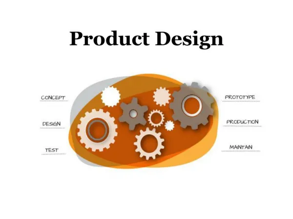
Product Design & Development Steps • End Use Requirement • a) Anticipated Structural Requirement • Loads- Stresses a material will be subjected • Rate of Loading • Duration of Loading • Impact Forces • Vibration • Foreseeable Misuse • b) Anticipated Environment • Temp Extremes • c) Assembly and Secondary Operation • d) Cost Limits • e) Regulation Standards compliances
Product Design & Development Steps • Establish Preliminary Design( Preliminary Concept Sketch and Sections) • Select the material( Expected End Use Requirement, Material Data Sheets) • a) Mechanical Properties used for essential component design calculations • b) Other Relevant Properties • 3 Modify Design as per the calculations results and desired function • a) Specific property balance of selected grade • b) Processing Limitation • c) Assembly Method • d) Cost of Modification
Product Design & Development Steps • CAD/CAE • Flow Analysis • Stress Analysis • 5 Prototype and Testing • 6 End Use Testing
INTRODUCTION • Plastics were considered as “Replacing Materials” • Today’s world plastics are unreplacable materials on the same level as the classic materials: • Primarily due to special combination of properties (profiles & material combinations) • Plastics offers solutions, that are not possible with classic materials (Electronics, Medical care, Automotive industries etc.) • Low weight, allows high accelerations & decelerations. • Weather resistance (Corrosion) is better than resistance of metallic materials. • Good Electrical Isolation properties (Housings of Electrical devices) • Low manufacturing costs, especially with injection moulding technology.
MATERIALS Metals (as Ores) High-Molecular (Makromolecular) materails Inorganic e.g. Glasses Organic Natural e.g. Wood Synthetic resp. Modified material Thermoplastics Thermosets Elastomers Crosslinkable (vulcanisible) elastomers Crosslinked:rubber Thermoplastic elastomers PLASTICS CLASSIFICATION :
Thermoplastics : • They are thread-like molecules (Linear & Branched) • They are always Deformable – Fusible – Soluble. • As degree of polymerisation (molecule length) increases strength & toughness increases, but flowability decreases. • They are further classified as • Amorphous thermoplastics & • Crystalline (Partially crystalline) thermoplastics
Amorphous Thermoplastics: • Bulky thread-like molecules, with unarranged interconnected macromolecular structures, similar to that of staples in a cotton pad. • Transparent (Exception) : Styrol – copolymers with Butatein like ABS. • Lower degree of Shrinkage & high precision can be achieved with less cost. • High elastic properties between melt & freezing (Glass transition) temperature makes it to be produced at low holding pressure to avoid demoulding problems & high internal stress. • They are more sensitive against solvents & the parts are more suspectable to stress cracking. Examples: Polycarbonate (PC) , Polyvinylchloride (PVC), Acrylonitrile – Butadiene – Styrene – Copolymer (ABS), etc.
Acrylonitrile – Butadiene – Styrene – Copolymer (ABS) : • Structure : amorphous Density : 1,03 – 1,07 g/cm³ Elastic-Modulus : ~ 2400 N/mm² • Properties : • High rigidity & toughness also at low temperature to – 40º C, • High Scratch resistance, High impact resistance, High suspectability to stress cracking • Temperature limits: • Short-Term ~ 100°C, Long Term ~ 85°C • Surface Quality : • High gloss surface can be achieved. • Natural colour: opaque, non-transperant • Manufacturing related properties : • Low shrinkage & low tendency to wrap, • Good Paintability & electroplatability. • Applications : • Automotive panels - (Interior & Exterior parts), etc.
Acrylonitrile – Butadiene – Styrene – Copolymer (ABS) : Applications
Polycarbonate (PC) : • Structure : amorphous Density : 1,20 – 1,24 g/cm³ Elastic-Modulus : ~ 2200 N/mm² • Properties : • High strength & Hardness, Toughness at low temperature. • High impact resistance, High suspectability to stress cracking • Temperature limits: • Short-Term ~ 135°C, Long Term ~ 100°C • Surface Quality : • High gloss surface can be achieved. • Natural colour: Transperant • Manufacturing related properties : • Low shrinkage & low tendency to wrap, • Good Paintability & electroplatability. • Applications : • Automotive panels - (Interior & Exterior parts), Headlights, Helmets, etc.
Polyvinylchloride (PVC) : • Structure : amorphous Density : 1,38 – 1,55 g/cm³ Elastic-Modulus : ~ 3000 N/mm² • Properties : • High hardness & stiffness. • High impact resistance at low temperature till -5°C, below this brittleness increases. • High suspectability to notch failure. • Temperature limits: • Short-Term ~ 70°C, Long Term ~ 60°C • Surface Quality : • High gloss surface can be achieved. • Natural colour: Transperant till Opaque • Manufacturing related properties : • Low shrinkage • High chemical resistance • Applications : • Ducts, Ventilation Channels, tubes, etc.
Crystalline Thermoplastics: • Bulky thread-like slim molecules, which are alligned or with each other. • Non transparent (translucent), naturally coloured good slip properties. • Higher degree of Shrinkage due to higher package of molecules. • Are less compressible than amorphous during hardening & freezing temperatures, hardly faces any demoulding problems. • Due to higher shrinkage may form voids during cooling. Examples: Polyethylene (PE), Polypropylene (PP), Polyamide (PA), Polyacetal (POM) etc.
Polyethylene (PE) : • Structure : Semi crystalline Density : 0.91 – 0.96 g/cm³ Elastic-Modulus : ~ 1200 N/mm² • Properties : • High stiffness & Hardness. Good elastic properties. • Practically unbreakable, ductile till -60°C • Temperature limits: • Short-Term ~ 135°C, Long Term ~ 80°C • Surface Quality : • High gloss surface can be achieved. • Natural colour: milky white • Manufacturing related properties : • No water absorption, High Shrinkage & tendency to warpage • High chemical resistance • Applications : • HR inserts, Ducts, Channels, etc.
Polypropylene (PP) : • Structure : Semi crystalline Density : 0.90 – 0.92 g/cm³ Elastic-Modulus : ~ 1450 N/mm² • Properties : • High stiffness & Hardness. Stability higher than PE. • High flexural fatigue strength. Low impact strength at low temperature. • Temperature limits: • Short-Term ~ 140°C, Long Term ~ 100°C • Surface Quality : • High gloss surface can be achieved. • Natural colour: Colourless shining through • Manufacturing related properties : • No water absorption, High Shrinkage & tendency to warpage • High chemical resistance • Applications : • Car – Coverparts (Interior & Exteriors), etc.
Polyamide (PA) : • Structure : Semi crystalline Density : 1.02 – 1.15 g/cm³ Elastic-Modulus : ~ 1300 - 2800 N/mm² • Properties : • High stiffness & impact strength. • Good friction & wear resistance • Temperature limits: • Short-Term ~ 170°C, Long Term ~ 110°C • Surface Quality : • High gloss surface can be achieved. • Natural colour: Translucent white-yellow • Manufacturing related properties : • Good flow properties & chemical resistance, • Not so good shrinkage. Tendency to warpage. • Applications : • Car – (Inner, Outer), Bearings, Gear wheels, etc.
Thermosets : They are closely crosslinked, that is the reason they are non – thermoplastic. They are always Non - deformable – Infusible – Insoluble. Examples: Epoxy (EP), Phenol-formaldehyde (PF), etc.
Elastomeres: They are loosely crosslinked, highly elastic & show very low plastic deformation. They are highly deformable –Insoluble. Examples: Natural Rubber (NR), Ethylen-Propylen rubber (EOM, EPDM), etc.
Design Guidelines REQUIREMENT (For what ?, strength, assy) MATERIAL SELECTION (Cost , Manuf Prosess,Temp conds, Strength, Safety) PACKAGING DATA & KINEMATICS ( From customer) DECIDING SNAP & SCREW FIXING LOCATIONS (Locking 6 deg. Of freedom, DFA ) FIX TOOLING DIRECTION (Die-Draw direction, Minimum silder’s and aesthetic requirement ) (Packaging data, strength requirement) DECIDING STRENGTHING RIBS,LOCATIONS & GEOMETRY DRAFT ANGLES,RIBS WALL THICKNESS RATIO (As per design guidelines)
Design Guidelines ( Minimum core thickness, Slider ejection space, Sharp corners etc.) TOOLING FEASIBILITY DRAFT ANALYSIS A & B SURFACES SECTIONS WITH PACKAGING THROUGH SNAP & RIBS ( Tolerance issues)
Design Guidelines Material Selection: The wide variety of injection moldable thermoplastics often makes material selection a difficult task. Factors governing material selection • Cost • Functionality • Assembly (Typically when bonded) • Temperature • Strength • Government Regulations. • Surface finish/aesthetic etc.
Design Guidelines Wall thickness/ Base thickness: Proper wall thickness determines success or demise of a product. Like metals injection molded plastics also have normal working ranges of wall thickness. This can be taken into consideration while deciding wall thickness. Factors to be considered while deciding wall thickness. • Structural strength of the part to be designed plays important role in deciding wall thickness. • Normal working ranges of wall from chart for particular material selected. • As a thumb rule 2.5mm. • Prior experience or bench mark parts can also be referred while deciding on wall thickness.
Design Guidelines Wall thickness/ Base thickness: Once nominal wall thickness is decided, following are some design rules which should be followed. • Maintain uniform wall thickness wherever possible which helps in material flow in mold, reduces risk of sink marks, Induced stresses & consideration of different shrinkage • For non-uniform wall thickness change in thickness should not exceed 15% of nominal thickness & should transition gradually. • At corner areas minimum fillet at inner side should be 50% of wall thickness.
Design Guidelines Core-Cavity-Slider directions & Parting lines : • It is always recommended first to decide upon the core-cavity direction. Generally core-cavity direction & parting line depends upon following parameters • The shape & function of the component. Shape in turn is governed by A- Surface, packaging/environment data. • Core-cavity & slider directions should be considered such that they do not appear on A-Surfaces, unless otherwise specified & accepted by the customer.
Design Guidelines Draft Angles (On component walls): Draft is necessary for ejection of part from the mold & are always Tooling (Die-Draw) & Slider direction. Recommended draft angle is minimum 1deg. Factors governing draft angle. • Surface finish – Highly polished mold requires less draft than an unpolished mold. • Surface Texture (Graining) – Draft increases with texture depth,normally 1 deg draft for every 0.025mm depth recommended. • Draw depth – To keep the draft angle to minimum as thumb rule draft angle – draw depth charts are followed & often design engineer should discuss with tool maker.
Design Guidelines Ribs : Ribs should be used when needed for stiffness & strength or to assist in filling difficult areas. For structural parts where sink marks are no concerns -Rib base thickness can be 75%-80% of adjoining wall thickness For appearance parts where sink marks are objectionable: With texture (Graining) - Rib base thickness should not exceed 50% of adjoining wall thickness for part. Without texture (Graining) - Rib base thickness should not exceed 30% of adjoining wall thickness. Some important points to consider while rib design. • Draft angle on ribs should be minimum 0.5 deg per side • Rib height should be 2.5 to 3 times of wall thickness for effective strength. Recommended to add multiple ribs instead of single large rib, Spacing between multiple ribs should be at least 2 times that of rib thickness. • Fillets at base of ribs should be 0.5mm Minimum.
Design Guidelines Bosses : Usually designed to accept inserts, self tapping screws, drive pins etc for use in assembling or mounting parts. Some important points to consider while Boss design: • The O.D of the boss should be ideally 2.5 times of screw diameter for self tapping screw applications. • If O.D exceeds 50% of adjoining wall thickness, thinner wall boss of O.D 2 times or less of screw diameter can be considered with supported by ribs. • Bosses should be attached to walls with ribs. Thickness at base of rib should not exceed 50% of adjoining wall thickness. • Boss inside & outside diameters should have 0.5 deg draft per side.
Design Guidelines Bosses :
Design Guidelines Coring : Coring in injection molding terms to addition of steel to mold for the purpose of removing plastic material in that area Coring is necessary to create Pocket or, Opening in the part or to reduce heavily walled section.
Design Guidelines Openings : Openings are desired in a part to eliminate sliders, cams, pullers, etc. to accommodate features like snaps. As general thumb rule 5deg angle in the area of mating of core & cavity is required.
Design Guidelines Assemblies : Types of assemblies : • Molded-in assembly • Chemical bonding assembly • Thermal welding assembly • Assembly with fasteners. Molded-in Assembly : (Snap fit, Press fit, molded in threads etc.) This is generally the most economical method of assembly. Assembly is fast, inexpensive & does not require any additional part or substance. Minimizes changes of improper assembly. Some times tooling becomes complex & expensive.
Design Guidelines Snap fit assembly :
Design Guidelines Snap fit assembly : Y = Deflection Q values to be referred from Material graphs Important points to remember : • Design for given assembly force or overlap length & material. • Deflection required to assemble the part should always be less than maximum deflection(strain) for safe design. • Snaps increase possibility of sliders wherever possible try to eliminate sliders by providing slot below snap or moving snap to outer edge of the part, if design permits.
Design Guidelines Press fit assembly : • Press fit design is more critical in plastics (Thermoplastics as they creep (Stress or Relax). • Good design should minimize stress on the plastic,by considering assembly tolerance between assembled parts & clamping force due to creep relaxation.
Design Guidelines Adhesive joints assembly : • Two similar or dissimilar plastics can be assembled in a strong leak-tight bond by using adhesives. • The choice of adhesive depends upon the application & the environment to which the part would be subjected. • Some of adhesives are Polyurethanes, Epoxies, Cyanoacrylates, Silicones etc.
Design Guidelines Bolts –Nuts - Screws : • Certain precaution must be taken while designing to reduce excessive compressive stress on the plastic. • Larger head screw or larger washer is preferred as that contact area increases & stress reduces.
Design Guidelines Molded in threads : • Coarse threads are preferred due to higher strength & torque limits. • Generally 0.8 – 0.9 mm relief should be provided to prevent high stress at the end of the threads. • To reduce the stress concentration minimum 0.25mm radius should be applied to the threads roots. • External threads should be as far as possible located on parting lines to avoid need of unscrewing mechanism. • Internal threads are usually formed by an unscrewing or collapse core.
Design Guidelines Self Tapping Screws : Further classified in 2 types Thread cutting & Thread forming • Thread cutting screw is most used on brittle plastics such as thermosets & filled (50%) thermoplastics. They should not be reinstalled • Thread forming screws is mostly used on thermoplastics. They can be reinstalled for 3 to 5 times. General Guidelines while using self-tapping fasteners: Thread engagement length 2.5 times screw diameter Boss diameter minimum 2 times of pilot hole diameter. Cored hole should have 0.25 ° to 0.5° draft. Holes should be counterbored or chamfered to a depth of 0.5mm to aid alignment & avoid cracking of boss. Sufficient clearance to be kept between screw end & bottom of the hole.
HOW SLIDERS & LIFTERS WORK ?