
Memory system
E N D
Presentation Transcript
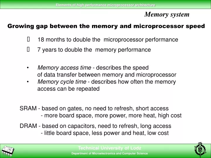
Memory system Growing gap between the memory and microprocessor speed • 18 months to double the microprocessor performance • 7 years to double the memory performance • Memory access time - describes the speed • of data transfer between memory and microprocessor • Memory cycle time - describes how often the memory • access can be repeated SRAM - based on gates, no need to refresh, short access - more board space, more power, more heat, high cost DRAM - based on capacitors, need to refresh, long access - little board space, less power and heat, low cost
Memory system Memory - the performance bottleneck • Memory fast enough to respond to every memory access request • Slow memory system with transfer improvements: wide busses and serial accesses • Combination of fast and slow memory systems, arranged so that the fast one is used more often then the slow one Another task for optimising compilers to arrange the code with the view of the fastest memory access DEC Alpha 21164 (500MHz) Internal registers 2ns Cache level 1 - on chip 4ns Cache level 2 - on chip 5ns Cache level 3 - off chip 30ns Main memory system 220ns Virtual memory on disk ms
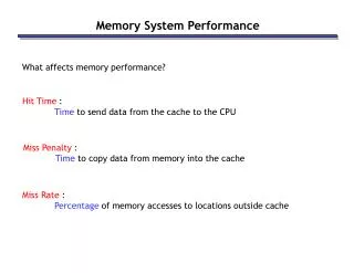
Cache basics Cache memory small amount of fast memory that store a subset of the main memory contents Operation principle: • When reading from memory, the microprocessor can find out whether the data is available in fast cache memory and transfer it, • otherwise it is fetched from main memory and placed in both • the microprocessor and cache • When writing to memory, the microprocessor can write both to cache and main memory or only to cache (i.e. write-through), or only to cache, where stored data is later transferred to main memory if this cache location is claimed by other data • Hit rate - fraction of accesses to cache memory in the total number of all memory accesses
CPU Increasing distance from CPU in access time L1 L2 ... Main system memory Size of memory at each level Cache basics Principle of locality • Temporal locality (locality in time) - if an item was referenced, it will be referenced again soon (e.g. cyclical execution in loops) • Spatial locality (locality in space) - if an item was referenced, items close to it will be referenced too (the very nature of every program - serial stream of instructions) High performance memory system - hierarchical organisation
Cache basics Cache organisation Main memory Cache Line 0 Line 1 Line 2 Line 3 etc... • The principle of locality is valid either for instructions or for data, • but there is no locality relation between demand for the both. • It is highly recommended to have two independent caches (Harvard Memory Architecture)
Cache problems Unit stride - the way of accessing the data from memory, so that the hit rate is maximal DO I = 1, 100000 SUM = SUM + A(I) END DO DO I = 1, 100000, 8 SUM = SUM + A(I) END DO Unit stride loop Non-unit stride loop Example: accessing the 2-dimensional table (FORTRAN) (successive elements of columns are stored sequentially in memory) REAL*4 A(200,200) DO I = 1, 200 DO J = 1, 200 SUM = SUM + A(I,J) END DO END DO REAL*4 A(200,200) DO J = 1, 200 DO I = 1, 200 SUM = SUM + A(I,J) END DO END DO Alphabetical, but non-optimal Optimal construction
Cache organisation Direct-Mapped Cache Line 0 Line 1 Line 2 Line 3 • Less significant part of the memory cell address (index) can be used directly to address data in cache • Most significant part (tag) is stored for each cache line and used to identify the part of main memory the data come from
Address from CPU Data Hit ? Tag Index Offset V Tag Data compare Cache organisation Direct-Mapped Cache V (1 bit) - indicates the validity of the cache line
Cache problems Cache thrashing When alternating memory references point to the same cache line, the cache entry is frequently replaced, lowering the performance. Example: 4KB direct-mapped cache The arrays’ size coincide with the cache size. The same elements from A and B will occupy exactly the same cache lines, causing repeated cache misses REAL*4 A(1024), B(1024) … DO I = 1, 1024 A(I) = A(I) * B(I) END DO
Cache organisation Set-Associative Cache - more flexible block placement The key to performance increase (and trashing reduction) is the more flexible placement of memory blocks by combining several direct-mapped caches. One-way set-associative (direct-mapped) Two-way set-associative Block Tag Data Block Tag Data Tag Data 0 0 1 1 2 2 3 3 The degree of associativity reduces the miss rate, at the cost of increase in the hit time and hardware complexity
Cache organisation Cache organisation Set-Associative Cache : four-way = = = = Hit ? Data
Cache organisation Fully Associative Cache Address Tag Data Tag Data Tag Data Tag Data Tag Data • The memory block can be placed in any cache line • Slower access - complicated internal circuitry • Demand on board space - each cache entry has a comparator • Memory needed for tags increases with associativity Choosing which block to replace • LRU (least recently used) - requires additional bits for each cache line, updated during each access • Random - candidates are selected randomly
Cache organisation Software managed caches Idea: transfer the data to cache before the processor needs it, so that the cache-fill time will be hidden Cache-fill time can be hidden and hopefully all memory references will operate at full cache speed. Prefetching - method of loading cache memory supported by some processors by implementing a new instruction. Prefetch instruction operates like any other instruction, except that processor doesn’t have to wait for the result DO I = 1, 100000, 8 PREFETCH( ARR(I + 8) ) DO J = 0, 7 SUM = SUM + ARR(I, J) END DO END DO Compilers can generate prefetch instructions when detects data access using a fixed stride
Cache organisation Post-RISC effects on memory references Ability of out-of-order and parallel execution gives the possibility to compensate for slow memory latency LOADI R6, 1000 set iterations LOADI R5, 0 set index LOOP LOAD R1, R2(R5) load from memory INCR R1 STORE R1, R3(R5) save in memory INCR R5 COMPARE R5, R6 check termination BLT LOOP branch if R5<R6 Several load/store instructions can be initiated without absolute stalling the program execution
Memory system Improving memory performance Two main obstacles: • Bandwidth - best possible steady-state transfer rate (usually when running a long unit-stride loop) • Latency - the worst-case delay during single memory access address address Bank 3 cache Main memory cache Bank 2 Bank 1 CPU CPU 32-256 Bank 0 data data Wide memory systems - high bandwidth Interleaved memory systems - lower latency