
**"PCB Assembly Guide for Thermometer Project Ver. 3.21"**
E N D
Presentation Transcript
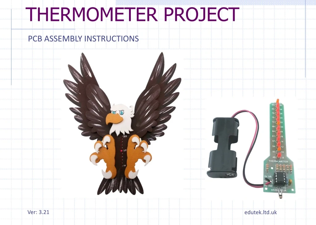
THERMOMETER PROJECT PCB ASSEMBLY INSTRUCTIONS Ver: 3.21 edutek.ltd.uk
ASSEMBLING THE PCB Hold the PCB as shown. Now go through the components to ensure you can identify each one
RESISTORS There are 7 resistors in all. R1 to R6 are all 33 ohms in value. They can be placed either way round. R7 is a 10K metal-film type which is blue with 5 coloured bands. It can also be inserted either way round.
IC HOLDER The IC holder is for the IC. It is optional but a good idea to use it. The holder has a notch at one end. This should face downwards. notch
CAPACITOR There is one 1uF ceramic dipped capacitor. It has the numbers “105” written on one side. This can be inserted either way round as it in a non-polarised type. It will be either blue or yellow in colour.
LEDs There are 12 LEDs, 9 red and 3 orange. They must be inserted the correct way round. The LED has a flat section on the rim of the LED to denote the negative. The long wire denotes the positive (+). Follow the markings on the PCB for each LED. Note each LED is inserted the opposite way round from the ones above and below it. These can be inserted all the way, or 6mm from the PCB to clear the height of the IC. Use a spacer (6mm) to hold the LEDs in position while you solder. 1mm thick card spacer shaped to grip PCB 6mm
THERMISTOR The Thermistor inserts below the IC holder. It can be inserted either way round. The wires are long so it can be soldered a small distance from the board and positioned where required. Make sure the wires do not touch together.
POWER LEADS The power leads from the battery holder are inserted up through the large hole in the PCB marked “Wire” and then back through the holes marked “+v” and “0v”. This prevents them from breaking off. Solder these wires to the pads underneath.
INTEGRATED CIRCUIT The IC can now be inserted into the IC holder. Make sure the notch on the case of the IC is facing downwards and all the pins are inserted correctly. notch To ease IC insertion, carefully pinch the rows of legs inwards slightly to help align them. ICs generally have their legs set slightly apart from manufacture.
POWER UP Insert the batteries and if all is well, the LEDs will light up quickly one after the other, to test they are all working. If two LEDs light up together, or one is not lighting up at all, check the orientation of the LED. If you have just built the thermometer and test it immediately, you will probably find the top orange LED on maybe even flashing. This is normal since the heat from the soldering iron has heated the circuit board and sensor. It should settle to the correct reading within 15 minutes.