Download
1 / 39
390 likes | 557 Vues
[M2] Traffic Control. Group 2 Chun Han Chen Timothy Kwan Tom Bolds Shang Yi Lin Manager Randal Hong. Overall Project Objective : Dynamic Control The Traffic Lights. Wed. Oct. 13. Status. Design Proposal Chip Architecture Behavioral Verilog Implementation

E N D
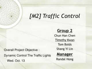
[M2] Traffic Control Group 2 Chun Han Chen Timothy Kwan Tom Bolds Shang Yi Lin Manager Randal Hong Overall Project Objective : Dynamic Control The Traffic Lights Wed. Oct. 13
Status • Design Proposal • Chip Architecture • Behavioral Verilog Implementation • Size estimates (Refined) • Floorplanning (Refined) • Behavioral Verilog simulated • Gate Level Design • Component Layout/Simulation • Chip Layout • Complete Simulation
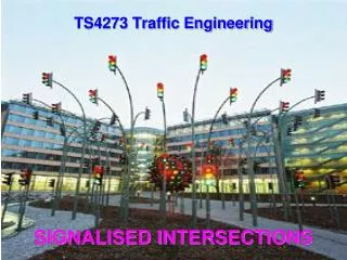
Structure for Light control FSM Arm1 [1:0] Arm2 [1:0] Combinational logic for output PEDESTRIAN complete SW arm Combinational logic for next state Encoder PED Decoder delay D-FFs next state [3:0] current state [3:0] Y2R, PEDBLINK etc. MUX Accumulator CLK Comparator
Behavioral V.S. Structuralthe results are matching module FSM(arm1, arm2, PEDESTRAIN, complete, state, nextstate, accum, delay, arm, SW, PED, clk, clear); output [1:0] arm1, arm2; output PEDESTRAIN, complete; output [3:0] state, nextstate, accum; output delay; //used for checking result input arm, SW, PED, clk, clear; wire [3:0] waiting; reg [3:0] T_Y2R = 4'd2; // define delay for yellow to red reg [3:0] T_PED = 4'd10;// define delay for pedestrain reg [3:0] T_PEDBLINK = 4'd5; // define delay for blinking reg [3:0] T_MAX = 4'd15; sig_control a(arm1, arm2, PEDESTRAIN, complete, state, nextstate, delay, arm, SW, PED, clk, clear); check_delay b(delay, accum, state, clk, T_Y2R, T_PED, T_PEDBLINK, T_MAX); endmodule module sig_control (arm1, arm2, PEDESTRAIN, complete, state, nextstate, delay, arm, SW, PED, clk, clear); input arm, SW, PED, clk, clear; output reg [1:0] arm1, arm2; output reg PEDESTRAIN, complete; output reg [3:0] state, nextstate; input delay; //used for checking result reg [3:0] T_Y2R = 4'd2; // define delay for yellow to red reg [3:0] T_PED = 4'd10;// define delay for pedestrain reg [3:0] T_PEDBLINK = 4'd5; // define delay for blinking reg [3:0] T_MAX = 4'd15; module decoder(s0, s1, s2, s3, s4, s5, s6, s7, s8, s9, s10, state); input [3:0] state; output s0, s1, s2, s3, s4, s5, s6, s7, s8, s9, s10; wire c0_1, c0_2, c1_1, c1_2, c2_1, c2_2, c3_1, c3_2, c4_1, c4_2, c5_1, c5_2, c6_1, c6_2, c7_1, c7_2, c8_1, c8_2, c9_1, c9_2, c10_1,c10_2; wire [3:0] state_b; NOT inv1(state_b[0], state[0]); NOT inv2(state_b[1], state[1]); NOT inv3(state_b[2], state[2]); NOT inv4(state_b[3], state[3]); //encoder for s0 NAND2 s0_1(c0_1, state_b[0], state_b[1]); NAND2 s0_2(c0_2, state_b[2], state_b[3]); NOR2 s0_3(s0, c0_1, c0_2); //encoder for s1 NAND2 s1_1(c1_1, state[0], state_b[1]); NAND2 s1_2(c1_2, state_b[2], state_b[3]); NOR2 s1_3(s1, c1_1, c1_2); //encoder for s2 NAND2 s2_1(c2_1, state_b[0], state[1]); NAND2 s2_2(c2_2, state_b[2], state_b[3]); NOR2 s2_3(s2, c2_1, c2_2); //encoder for s3 NAND2 s3_1(c3_1, state[0], state[1]); NAND2 s3_2(c3_2, state_b[2], state_b[3]); NOR2 s3_3(s3, c3_1, c3_2); //encoder for s4 NAND2 s4_1(c4_1, state_b[0], state_b[1]); NAND2 s4_2(c4_2, state[2], state_b[3]); NOR2 s4_3(s4, c4_1, c4_2); //encoder for s5 NAND2 s5_1(c5_1, state[0], state_b[1]); NAND2 s5_2(c5_2, state[2], state_b[3]); NOR2 s5_3(s5, c5_1, c5_2); Therefore, Start to draw schematics…
Flow Control Simulation 0 arm0=x, arm1=x, ped=x 500 arm0=0, arm1=0, ped=0 1000 arm0=2, arm1=0, ped=0 31000 arm0=1, arm1=0, ped=0 35000 arm0=3, arm1=0, ped=0 46000 arm0=1, arm1=0, ped=0 50000 arm0=0, arm1=2, ped=0 79000 arm0=0, arm1=1, ped=0 83000 arm0=0, arm1=3, ped=0 94000 arm0=0, arm1=1, ped=0 98000 arm0=2, arm1=0, ped=0
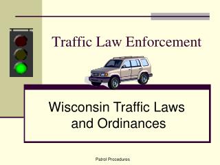
2:1 MUX 110 Reg X 10 β 110 11 11 X 10 Reg X 10 11 2:1 MUX 11 1 1 ARM 11 11 ARM 11 16:1 MUX 1 1 1:16 De-MUX ROM 11 q0,q1: X 2 n0 Dot Lint to FSM 11 Shifting n1 n0 = 0 11 11 X 9 β n0 ENTER 11 11 n1 β n1 = 0 11 q0 11 q1 F F <= 0 12 Accum 11 Reg 11 11 Q_len 11 bit ½ 11 Reg X 9 12 bit Reg X1 n_avg 11 4 s0,s1: X 2 Sel ALU 11 11 X 1 OUT / LEFT 11 12 111 11 s0 αn0-n1 11 s1 αn0 Accum 11 Reg 11 11 α0 q0-s0 11 α1 11 q1-s1 N_avg Q(αn0-n1) αn0-n1 αn0 11 2:1 MUX α0,α1: X 2 q0-s0 4 User Input q1-s1 11 11 11 Reg Q(αn0-n1) Sel ROM 2 4 Sel_ALU Sel 8 X 8 : Dot Line to Comparator R,r, RL,rl for Arm1 Arm2 2:1 MUX 8 X 8 8X8 User Input R,r 11 Reg 8X8 11 11 ½ ROM 11 11 11 11 User Input Q 11 11 Reg 11 8 : 1 MUX Trigger, when cars go left turn System Clock 1 1 Sel_D 2 ARM 1 System Clock R & r, R_L& r_L 2 Sel_ALU 1 8 8 8 X 8 3 Sel_C 2 ARM 2 8 Clk Div. Accmu Reg 4X3 Sel FSM FSM 1 1 PED INT. Compar SW 1 8 8 3 1 ARM 1 Accmu Reg Left-Turn Counter 8 Sel_C PED 1 Complete n0 1 Shifting 8 n1 CLK 1 8 F 8 T 1 Clear 1 1 Ser_D 2 : 1 MUX Operation Data Input Initial Values Selection R, r, R_L, r_l Light Control FSM Flow Control FSM Clock T, Left-Turn Counter
Block Size Estimates • 530um x 460 um • ~ 1.15 : 1 aspect ratio • .243 mm^2 area • .11 Transistor Density
Estimate Block Size From Layout : Some Basic Layout Ratio: Register (1bit) 16.6 6.6 2X1 MUX 13.5 6.5 • Asterisk(*) : • no precise layout outline now.
2:1 MUX 110 Reg X 10 β 110 11 11 X 10 Reg X 10 11 2:1 MUX 11 1 1 ARM 11 11 ARM 11 16:1 MUX 1 1 1:16 De-MUX ROM 11 q0,q1: X 2 n0 Dot Lint to FSM 11 Shifting n1 n0 = 0 11 11 X 9 β n0 ENTER 11 11 n1 β n1 = 0 11 q0 11 q1 F F <= 0 12 Accum 11 Reg 11 11 Q_len 11 bit ½ 11 Reg X 9 12 bit Reg X10 n_avg 11 4 s0,s1: X 2 Sel ALU 11 11 X 1 OUT / LEFT 11 12 111 11 s0 αn0-n1 11 s1 αn0 Accum 11 Reg 11 11 α0 q0-s0 11 α1 11 q1-s1 N_avg Q(αn0-n1) αn0-n1 αn0 11 2:1 MUX α0,α1: X 2 q0-s0 4 User Input q1-s1 11 11 11 Reg Q(αn0-n1) Sel ROM 2 4 Sel_ALU Sel 8 X 8 : Dot Line to Comparator R,r, RL,rl for Arm1 Arm2 2:1 MUX X 8 8 X 8 8X8 User Input R,r 11 Reg 8X8 11 11 ½ ROM 11 11 11 11 User Input Q 11 11 Reg 11 8 : 1 MUX Trigger, when cars go left turn System Clock 1 1 Sel_D 2 ARM 1 System Clock R & r, R_L& r_L 2 Sel_ALU 1 8 8 8 X 8 3 Sel_C 2 ARM 2 8 Clk Div. Accmu Reg 4X3 Sel FSM FSM 1 1 PED INT. Compar SW 1 8 8 3 1 ARM 1 Accmu Reg Left-Turn Counter 8 Sel_C PED 1 Complete n0 1 Shifting 8 n1 CLK 1 8 F 8 T 1 Clear 1 1 Ser_D 2 : 1 MUX Transistor Counts T: 1540 X 2 T: 1320 T: 132 T: 1980 X 2 T: 1980 T: 12 T: 4848 T: 1526 T:308 X 2 T:154 X 2 T:308 X 2 T:154 X 2 T:132 X 2 T:154 X 2 T: 96 X 8 T:896 T: 832 T: 882 T:96 T:154 T: 672 T: 240 T:308 T:112 T:308 T:112 T: 96
Current Version Wire routing on each block
Metal Directionality • M1, M2 • Local connect • VSS & VDD • M3,M4 • System Clock • Global Routing • Control Signals
Block Metal Layers That Have Been Used 16:1,2:1 MUX/DEMUX M1 & M2 2:1 MUX Array (x110) M1 & M2 &M3 & M4 Register M1 & M2 11-bit Reg.+12-bit Reg. M1 & M2 &M3 & M4 Accumulator M1 & M2 Adder/Subtrator M1 & M2 Multipliers M1 & M2 Selection Signal M3 & M4 Wire Pre-Decision on Block In current floorplan, there are some useless space between block, we thought metal 4 could utilize more efficiently to decrease the total area.
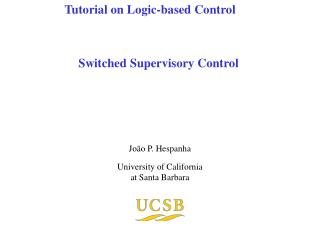
Light Control FSM – Combinational Logic for Next State Complicated wire routing. Need to be careful when doing layout
Light Control FSM – Combinational Logic for Output
Light Control FSM – Check Delay Circuit(1) Accumulator
Light Control FSM – Check Delay Circuit(2) MUX & Comparator MUX Comparator
Light Control FSM – Other Control Circuit Counter Reset SEL (For MUX) Complete (To the other FSM)
Light Control FSM – TOP Level 1. Didn’t finish overall simulations for all blocks. 2. Try to do that as soon as possible to compare the results of structure Verilog.
Issues • Some Cadence software stuff • Which simulator to use? • Am I using the right Cadence version? • Transistor Sizing? • Using 540/270 for everything at the moment
Issues Timing control may be a problem. May need to add additional buffers to drive loads at next stage. Is that required to do sizing by calculating logic effort? (Since speed is not an issue)
2:1 MUX 110 Reg X 10 β 110 11 11 X 10 Reg X 10 11 2:1 MUX 11 1 1 ARM 11 11 ARM 11 16:1 MUX 1 1 1:16 De-MUX ROM 11 q0,q1: X 2 n0 Dot Lint to FSM 11 Shifting n1 n0 = 0 11 11 X 9 β n0 ENTER 11 11 n1 β n1 = 0 11 q0 11 q1 F F <= 0 12 Accum 11 Reg 11 11 Q_len 11 bit ½ 11 Reg X 9 12 bit Reg X1 n_avg 11 4 s0,s1: X 2 Sel ALU 11 11 X 1 OUT / LEFT 11 12 111 11 s0 αn0-n1 11 s1 αn0 Accum 11 Reg 11 11 α0 q0-s0 11 α1 11 q1-s1 N_avg Q(αn0-n1) αn0-n1 αn0 11 2:1 MUX α0,α1: X 2 q0-s0 4 User Input q1-s1 11 11 11 Reg Q(αn0-n1) Sel ROM 2 4 Sel_ALU Sel 8 X 8 : Dot Line to Comparator R,r, RL,rl for Arm1 Arm2 2:1 MUX 8 X 8 8X8 User Input R,r 11 Reg 8X8 11 11 ½ ROM 11 11 11 11 User Input Q 11 11 Reg 11 8 : 1 MUX Trigger, when cars go left turn System Clock 1 1 Sel_D 2 ARM 1 System Clock R & r, R_L& r_L 2 Sel_ALU 1 8 8 8 X 8 3 Sel_C 2 ARM 2 8 Clk Div. Accmu Reg 4X3 Sel FSM FSM 1 1 PED INT. Compar SW 1 8 8 3 1 ARM 1 Accmu Reg Left-Turn Counter 8 Sel_C PED 1 Complete n0 1 Shifting 8 n1 CLK 1 8 F 8 T 1 Clear 1 1 Ser_D 2 : 1 MUX